Complete Diesel Generator Operation & Maintenance Management Guide
The core philosophy of diesel generator operation management is anchored in four principles: prevention first, routine maintenance, standardized operation, and safety above all. Generator operation management is a systematic endeavor that spans the full equipment lifecycle—from installation and commissioning through to retirement.
Implementing rigid Standard Operating Procedures (SOPs) and comprehensive logging protocols directly extends equipment service life, mitigates unexpected power outages, and ensures generator sets start reliably, operate safely, and supply clean power when emergency standby or prime power is demanded.
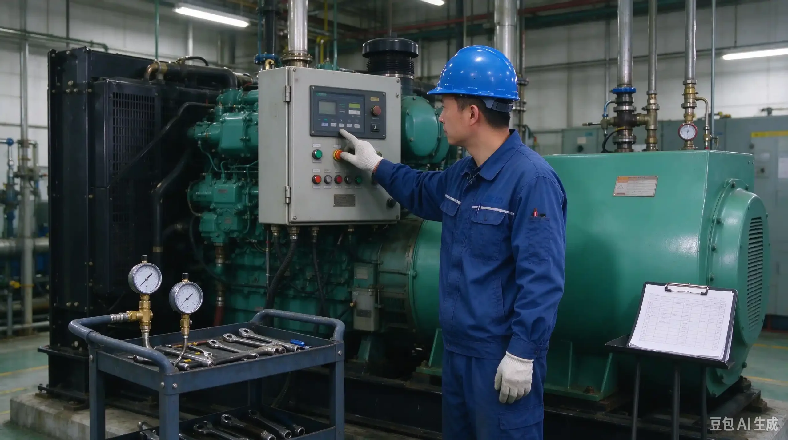
1. Pre-Operational Inspection Protocols
Before initiating any start cycle, operators must complete a rigorous multi-point visual and mechanical check to identify potential hazards and ensure operational readiness.
1.1 General and Environmental Inspection
- Site Cleanliness: Ensure the generator enclosure and surrounding perimeter are free of debris, oil spills, rags, and combustible materials.
- Structural Integrity: Inspect mounting baseplates, vibration isolators, pipe fittings, and electrical connections for loose hardware, damage, or active fluid leaks.
- Ventilation Clearance: Verify that intake louvers and exhaust ducts are unobstructed to ensure unrestricted airflow for engine combustion and cooling.
1.2 Subsystem Inspections
- Fuel System: Verify adequate diesel fuel levels in the day tank. Inspect fuel supply lines, lift pumps, and primary/secondary filters for leaks. Bleed trapped air from the fuel system if filters or fuel lines have been recently replaced.
- Lubrication System: Check oil level via the engine dipstick; fluid must sit firmly between the
MINandMAXhash marks. Inspect oil color and viscosity; replace degraded oil immediately. - Cooling System: Inspect coolant level within the expansion tank or radiator header. Add recommended glycol coolant mixtures if low. Warning: Never open the pressure cap on a hot radiator. Check water pump seals and hose connections for leaks.
- Starting Battery System: Measure battery terminal voltage using a multimeter—ensure a minimum reading of 12.6V for 12V systems or 25.2V for 24V systems. Confirm cable terminals are clean, tight, and greased to prevent corrosion.
- Electrical Output & Load Interface: Ensure the main output circuit breaker is in the
OFF(Open) position prior to starting under manual mode. Verify load cables are securely terminated and insulation remains intact.
2. Operational Procedures and System Management
2.1 Single-Unit Operating Sequence
- Pre-heating (If Equipped): In cold ambient environments, activate coolant or intake air preheaters via the control screen to warm up the cylinder block before cranking.
- System Power-Up: Turn the control panel key switch from
OFFtoON. Verify display backlighting illuminates and digital controllers energize. - Engine Startup:
- If configured with idle/full-speed toggle options, start in idle mode. Limit idle warm-up runs to under 5 minutes to prevent carbon build-up.
- Press the Start button. Crank the engine for a maximum of 5–10 seconds per attempt (do not exceed 30 seconds continuous cranking). If the engine fails to start, pause for at least 2 minutes before retrying to protect the starter motor and battery.
- Note: Never attempt to hotwire or bypass the control panel to initiate a manual start.
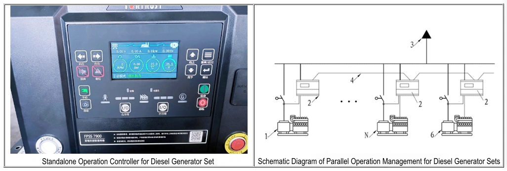
- Loaded Running & Parameter Monitoring: Once the engine reaches rated speed and output voltage/frequency stabilizes, close the output circuit breaker to apply load. Regularly monitor control display parameters—including oil pressure, coolant temperature, AC voltage, current, and frequency—and log data into the operator logbook.
- Emergency Shutdown: Press the red Emergency Stop Button (E-Stop) ONLY during severe equipment malfunctions or electrical hazards. Avoid using E-stop for normal operational shutdowns.
- Normal Shutdown Procedure: Open the output circuit breaker to disconnect load. Allow the engine to run unloaded at rated speed for 3–5 minutes to cool down turbine housings and internal components. Press the Stop button on the panel to turn off the engine, then turn the key switch to
OFF.
2.2 Multi-Unit Paralleling Management
For mission-critical applications like data centers or large industrial plants, multiple generator sets operate in parallel using a Master Controller and individual Generator Controllers linked via high-speed communication buses.
- Automatic Demand-Based Power Management: Upon utility power failure, the master controller signals individual generator controllers to start a calculated number of units matching real-time load requirements, keeping an additional unit online in hot-standby (N+1 redundancy).
- Synchronization Checks: Manual or automatic paralleling requires absolute matching across four conditions before closing tie breakers: equal voltage, identical frequency, correct phase sequence, and synchronized phase angle.
2.3 Operational Logging Standard
Accurate logging provides vital trend data for predictive diagnostics. Every run cycle should be recorded in a standardized log sheet.
| Time | Engine Parameters | Generator Parameters | Fault Record | Operator | Remarks | |||||
|---|---|---|---|---|---|---|---|---|---|---|
| Start/Stop Time |
Cumulative Operating Hrs
|
Oil Pressure Bar | Water Temperature ℃ | Voltage V | Current A | Frequency HZ | Power KW | |||
3. Post-Shutdown Protocols, Safety Rules & Maintenance
3.1 Post-Shutdown Checklist
- Inspect engine bay for post-run oil, fuel, or coolant leaks (“Three Leaks”).
- Close manual fuel supply valves if going offline for extended periods.
- Verify generator main output circuit breaker is locked in the open position.
- Reset auto-start standby units back to
AUTOreadiness mode for emergency deployment. - For long-term storage or major maintenance, disconnect battery negative terminals and drain fluids as required.
3.2 Comprehensive Safety Protocols
- Personnel Safety: Only trained, certified personnel should operate or service generator sets. Wear PPE and avoid touching hot exhaust components (turbocharger, exhaust manifold). Disconnect battery cables before servicing electrical assemblies.
- Environmental & Electrical Safety: Maintain proper room ventilation to prevent toxic Carbon Monoxide (CO) buildup. Collect waste oil and filters in compliant disposal containers. Always follow strict Lockout/Tagout (LOTO) procedures during electrical maintenance.
3.3 Preventative Maintenance Schedule (Hours-Based)
| Maintenance Interval | Required Maintenance Tasks |
|---|---|
| Daily / Weekly | Execute full pre-start checklist; check battery voltage and fluid levels. |
| 50 – 100 Hours | Initial break-in maintenance: Replace engine oil and lube oil filter. |
| 250 – 500 Hours | Replace engine oil, lube oil filter, and fuel filters. Inspect/clean air filter element. Check belt tension and coolant protection levels. |
| 1000 – 1500 Hours | Replace all filters (oil, fuel, air). Flush cooling system and replace coolant. Inspect turbocharger, starter motor, and alternator bearings. Calibrate valve clearances and injectors. |
| Annual Maintenance | Perform full load-bank testing (min. 4 hours at high load), recalibrate control sensors, and test safety protection trips regardless of run hours. |
| Extended Idle Rule | Run idle standby generators under no-load for 30 minutes monthly; perform an annual load-bank test to burn off carbon deposits (wet stacking). |
Message us for more information