作者归档:jzxadmin

250kVA/200kW Diesel Generator (Cummins NT855-GA) APC200GF-1 | Allian Power

GENERATOR SET SPECIFICATIONS
Standby Power 250 kVA/200 kW
Prime Power 225 kVA/180 kW
Voltage 380/220V, 400/230V, 415/240V
Frequency 50 Hz
Speed 1500 rpm
ENGINE
Manufacturer Cummins
Engine Model NT855-GA
ALTERNATOR
Stamford UCDI274K14 200KW
Leroy Somer TAL-A46-D 200KW
Marathon MP-200-4A
Allian Power APF200 200kW
Type 100% Copper, Brushless, Self-Excited
Protection Class IP23 Protection
CONTROL SYSTEM & ENCLOSURE
Control Panel Manual/Autostart Optional, Brand: Deep Sea, SmartGen, ComAp
Construction Highly Corrosion Resistant Construction with Shock Absorbers
Enclosure Features Weatherproof & Soundproof Canopy with Integrated Fuel Tank & Exhaust Silencer

Cummins Diesel Generator Cooling System Maintenance & Coolant Guide

Cummins diesel generator sets primarily utilize a closed-loop liquid cooling system equipped with a built-in, engine-driven fan. Maintaining precise temperature control within this circuit is critical to preventing thermal stress, reducing component wear, and ensuring uninterrupted power deployment.

A standard Cummins cooling loop comprises several heavy-duty components working in tandem:

  • Water pump and internal cylinder block cooling jackets
  • Thermostat and bypass piping
  • Radiator core, heavy-duty hoses, and lines
  • Oil cooler and integrated coolant filters (on specified models)


For custom or non-standard configurations (such as remote cooling systems), the traditional radiator is replaced by a high-efficiency heat exchanger, accompanied by a surge tank and a remote cooling fan. Technical Note: If the remote fan is installed at a high elevation, a transition expansion tank must be integrated into the loop to mitigate excessive internal pressure and protect the heat exchanger core from structural fatigue.

CRITICAL NOTICE: Airborne dust, grease, and debris adhering to the radiator fins will drastically impair thermal dissipation. In high-dust environments, regular radiator core flushing is mandatory to prevent engine overheating.

1. Coolant Specifications & Selection Criteria

Engine coolant is not just “water”—it serves three vital engineering functions:

  1. Maximizes heat transfer capacity across all operational loads.
  2. Prevents cavitation erosion and chemical corrosion on internal metallurgy and elastomeric seals.
  3. Provides robust anti-freezing protection in extreme climates.

Water Quality & Antifreeze Blending

  • Water Standards: The base water must have a stable pH value between 6 and 8. Distilled or deionized water is highly recommended to prevent scale buildup.
  • Freezing Climates: In cold regions, a premixed antifreeze solution matching the local minimum ambient temperature is required. Always blend the water and ethylene glycol evenly in a separate container before pouring it into the radiator to eliminate thermal stratification. High-quality antifreeze also raises the boiling point, preventing “boil-over” during peak load periods.
  • Non-Freezing Climates: In tropical or temperature-controlled environments, a dedicated rust inhibitor can substitute for antifreeze. This maximizes thermal efficiency while protecting internal water jackets. After the initial fill, run the genset until it reaches normal operating temperature to activate the anti-corrosive protective film.

Maintenance Interval: Flush and replace the coolant every two years. Over time, chemical additives deplete, leading to sediment accumulation, rust risks, and erratic water temperature sensor readings.

2. Coolant Draining, Flushing & Refilling Protocols

Draining & Flushing

Never attempt to drain the cooling system while the engine is hot. Shut down the generator and allow the block to cool completely. Slowly remove the radiator filler cap to relieve residual pressure, then open both the radiator drain valve and the engine block drain plugs. If equipped, spin off the old coolant filter and fit a genuine replacement. Flush the circuit thoroughly with clean water until the discharge runs perfectly clear.


Refilling & Air Bleeding

Tighten all drain plugs before refilling. Pour the premixed coolant into the system slowly to prevent air pockets from forming within the cylinder head water jackets.

Air must be vented through the main filler neck and the cylinder head air release valves (typically located at the highest point of the cooling circuit, near the thermostat or temperature sensor). If the system includes an auxiliary jacket heater, open its control valve completely during the fill process. Pro-Tip: If an air release valve is unavailable, slightly loosen the water temperature sensor until liquid flows out, then re-torque it immediately.

Fill the radiator until the liquid level sits exactly 5 cm (2 inches) below the top welding seam or aligns with the level sight glass. Do not crank the engine until venting is complete. Once filled, start the genset, let it reach operating temperature, recheck the level, and top off with identical coolant specifications if necessary. For filtered loops, ensure the filter valve handle is turned to the vertical (open) position prior to formal operation.

3. Optional Accessories: Coolant Preheaters

To guarantee rapid emergency startup and seamless load acceptance in sub-zero environments, Cummins generator sets can be configured with two types of jacket preheaters:

  1. AC-Powered Electric Preheaters: Utilizes shore/mains power to maintain constant engine block temperatures during standby mode.
  2. DC-Powered Fuel-Fired Preheaters: Draws diesel directly from the generator’s fuel system, making it ideal for remote or off-grid sites without reliable AC power.

All preheaters supplied by Allian Power come factory-installed and pre-commissioned. Users only need to connect the corresponding power supply or fuel line according to the wiring schematics to activate automatic cold-start protection.

AllianPower Delegation Visits Malaysia-China Chamber of Commerce (MCCC), Achieving Practical Outcomes

Kuala Lumpur, September 23, 2005

​On the morning of September 23, the Qingdao Allian Power Delegation, together with China Council for the Promotion of International Trade – Shandong Provincial Sub-Council (CCPIT-Shandong) delegation,was invited to visit the Malaysia-China Chamber of Commerce (MCCC). The delegation was warmly welcomed by their Malaysian counterparts, leading to a candid, efficient, and highly fruitful communication.

The MCCC, headquartered in Kuala Lumpur and established in 1990, is an independent, non-governmental, non-profit, and multi-racial business association. Its mission is to build bridges for Malaysia-China economic and trade cooperation, promote bilateral trade and investment, and strengthen ties with governmental and business organizations in both countries, playing a vital role in facilitating commercial collaboration.

In his welcome address, Mr. Lim Chee Kiat, President of the MCCC Chapter, commended Shandong Province as a leading economic powerhouse in China, highlighting its forefront position in economic innovation, industrial production, intelligent machinery, agricultural development, industrial upgrading, and internationalization. Noting the long-standing and comprehensive cooperation between Malaysia and Shandong, he expressed confidence that enterprises from both sides will forge more collaborations under the new “Golden 50 Years” of China-Malaysia relations.

Mr. Chia Chong Seng, Secretary-General of the MCCC, thanked the CCPIT-Shandong delegation for their special visit, stating that their journey from Shandong demonstrated the high importance Shandong enterprises place on the Malaysian market. He affirmed that the chambers will deepen their cooperation to build a solid bridge for business collaboration between the two regions.

Ms. Zhang Yuanyuan, Central Committee Member and Vice Chairman of the International Business Committee of the MCCC, extended a sincere welcome to the Shandong delegation and provided a detailed introduction to the MCCC’s operations and structure. She reiterated the chamber’s commitment to working hand-in-hand with Chinese partners to foster enterprise-level cooperation.

Mr. Zhou Liang, head of the CCPIT-Shandong delegation, expressed sincere gratitude for the warm reception and briefed on the development status of Shandong’s key industries. Against the strategic backdrop of building a “high-level China-Malaysia community with a shared future,” as guided by the top leaders of both nations, he conveyed confidence that cooperation between Shandong and Malaysian enterprises in machinery manufacturing, equipment upgrading, and energy power will deepen and reach new heights.

Representatives from both sides engaged in targeted and in-depth discussions on industry development and future cooperation. The active and constructive dialogue enhanced mutual confidence and consensus, resulting in a series of concrete cooperative outcomes.

The meeting concluded with an exchange of commemorative gifts and a group photo.

The Qingdao Allian Power delegation, including Executive Vice President Mr. Eric Wu, Vice President and Chief Engineer Mr. Zhang Sijing, and Deputy Chief Engineer Mr. Kong Lingzhou, attended the exchange. New procurement intentions were confirmed with Malaysian partners during the event.

Nigerian Embassy Delegation Visits Allian Power to Advance Power Grid Partnerships

A high-level diplomatic delegation led by Ambassador Babagana Wakil, the Chargé d’Affaires ad interim of the Embassy of Nigeria in China, recently visited Qingdao to hold strategic talks with Allian Power. The discussions centered on deploying advanced supplementary power systems to support Nigeria’s national power grid and drive sustainable industrial growth.

Mr. Eric Wu, General Manager of Allian Power, alongside Mr. Charles Liu, Marketing Department Manager, officially received the diplomatic delegation. Both parties engaged in comprehensive exchanges regarding local manufacturing investment, microgrid infrastructure, and the utilization of natural gas for off-grid power generation.

Strengthening Nigeria’s Off-Grid Infrastructure & Mining Sectors

During the summit, Ambassador Babagana Wakil extended an official invitation to Allian Power to invest and establish local manufacturing facilities in Nigeria. Highlighting Nigeria’s vast mineral reserves and abundant natural gas resources, the Ambassador emphasized the critical role of heavy-duty generator sets as a reliable supplementary power source for remote mining operations.

Furthermore, utilizing localized natural gas to fuel these generator sets offers an economical, safe, and eco-friendly electricity alternative for regions currently bypassed by the national grid. Ambassador Wakil highly commended Allian Power’s technological innovation, noting that Nigeria prioritizes strategic energy partnerships with China. He affirmed that Allian Power’s technical expertise and field experience are pivotal for accelerating Nigeria’s emerging industrial sectors and exploring new pathways for sustainable development.

Allian Power’s Commitment to the “Belt and Road Initiative”

Welcoming the delegation, Mr. Eric Wu expressed his gratitude and highlighted Nigeria’s enduring partnership with China under the “Belt and Road Initiative.” He reaffirmed that Allian Power is fully prepared to leverage its engineering expertise in the energy sector to help Nigeria build robust, clean energy infrastructure in areas lacking urban power grid coverage.

Looking ahead, Allian Power aims to broaden its strategic footprint in Nigeria, contributing directly to the global transition toward green, low-carbon, and highly resilient energy ecosystems.

AllianPower attend China (Shandong) – Malaysia Economic and Trade Cooperation Conference Held in Kuala Lumpur

KUALA LUMPUR, September 23, 2025​ – The China (Shandong) – Malaysia Economic and Trade Cooperation Exchange Meeting was successfully convened at W Hotel in Kuala Lumpur, Malaysia.


The event featured addresses and speeches by distinguished guests including Mr. Lin Wu, Secretary of the Shandong Provincial Committee of the Communist Party of China and Director of the Standing Committee of the Shandong Provincial People’s Congress; Mr. Fan Bo, Standing Committee Member of the Shandong Provincial Party Committee and Secretary-General; Mr. Zheng Xuefang, Chargé d’Affaires ad interim of the Embassy of the People’s Republic of China in Malaysia; YB Mr. Chang Lih Kang, Minister of Science, Technology and Innovation of Malaysia; Tan Sri Dato’ Sri Dr. Low Kian Chuan, Chairman of the Malaysia-China Business Council; Mr. Rashidi Said, Senior Director of the Bilateral Economic Relations Division, Ministry of Investment, Trade and Industry of Malaysia; and Dato’ Ng Yek Pyu, President of the Associated Chinese Chambers of Commerce and Industry of Malaysia. Senior officials from relevant cities in Shandong Province and heads of relevant provincial departments also attended the meeting.

This Conference was a significant event during the Shandong Economic and Trade Delegation’s visit to Malaysia. Mr Zhang Sijing, President & Chief Engineer of Allian Power, Mr. Eric Wu, Vice President & International Director of Allian Power, was honored to be invited to participate and represented Allian Power in a signing ceremony with a Malaysian partner company.

In his speech, Mr. Zheng Xuefang, Chargé d’Affaires ad interim of the Chinese Embassy in Malaysia, stated that Shandong is not only a crucial cradle of Chinese civilization but also one of China’s most economically dynamic provinces. He highlighted Shandong’s robust industrial foundation and comprehensive range of manufacturing sectors, with “Shandong Manufacturing” and “Shandong Creation” gaining global recognition. Noting the vitality of Shandong’s outward-oriented economy and Malaysia’s role as a key regional hub for trade and investment, Mr. Zheng emphasized the shared commitment of both sides to seeking development through openness and mutual benefit through cooperation, characterizing them as strong partners in the Belt and Road Initiative. He described the collaboration between Shandong and Malaysia as a partnership for industrial upgrading and kinetic energy conversion, an alignment of the principles of open cooperation and mutual benefit, and a dialogue between the birthplace of Confucian civilization and a significant representative of Islamic civilization. With this year marking the beginning of a new “Golden 50 Years” for China-Malaysia relations, Mr. Zheng expressed confidence that Shandong-Malaysia cooperation is poised to embrace new opportunities. He encouraged more Shandong enterprises to invest in Malaysia and welcomed more Malaysian businesses to explore opportunities in Shandong.

Mr. Lin Wu, Secretary of the Shandong Provincial Party Committee, noted that economic and trade ties between Shandong and Malaysia are growing increasingly close, with Malaysia having become Shandong’s largest trading partner within ASEAN. He expressed Shandong’s willingness to work with Malaysia to deepen collaboration in industrial and supply chains, continuously expand two-way investment, and strengthen cooperation in sectors such as chemicals, energy, and electronic information. He also proposed exploring broader trade markets by vigorously developing new forms of business like cross-border e-commerce to cultivate more growth points; jointly enhancing maritime cooperation advantages by strengthening collaboration in port construction, marine transportation, and marine industry synergy and innovation to bolster the blue economy; and enhancing cooperation in emerging fields by actively aligning with Malaysia’s strategies such as its digital plan and energy transition, deepening collaboration in artificial intelligence, integrated circuits, and clean energy development, thereby injecting strong momentum into each other’s development.

YB Mr. Chang Lih Kang, Minister of Science, Technology and Innovation of Malaysia, emphasized Malaysia’s commitment to driving energy transition and sustainable growth, actively developing its hydrogen economy, renewable energy technologies, and biotechnology. He expressed hope that both sides would strengthen cooperation in advanced materials, smart agriculture, and aquaculture, combining Malaysia’s innovation ecosystem with Shandong’s industrial strengths to contribute to sustainable development for both countries and the region.

Allian Power has always placed high importance on cooperation and development within the ASEAN region, particularly in Malaysia. Over the years, the company has provided product resources – including power machinery, energy equipment, diesel generators, gas generators, and power engine, agricultural equipment – to dozens of Malaysian clients. These products align with Shandong’s key industrial strengths and have earned a strong reputation among clients both domestically and internationally, making a unique contribution to Shandong-Malaysia commercial cooperation. In recent years, Allian Power has actively seized opportunities presented by national strategies like the Belt and Road Initiative and RCEP. Through global layout and industrial synergy, the company has promoted the export of its products and services to over 60 countries and regions worldwide, achieving healthy development through integrated domestic and international cycles. Moving forward, Allian Power will adopt a broader global perspective, proactively seize opportunities arising from economic transformation and innovation-driven development, further accelerate its “Going Global” strategy, continuously expand its business coverage, foster new competitive advantages in international cooperation, explore new spaces for international collaboration, and actively contribute to promoting high-quality development of the Belt and Road Initiative.

The China (Shandong) – Malaysia Economic and Trade Cooperation Conference was organized by the Shandong Provincial People’s Government, the Ministry of Investment, Trade and Industry of Malaysia, and the Malaysia-China Business Council. It was undertaken by the Department of Commerce of Shandong Province, and co-organized by the National Chamber of Commerce and Industry of Malaysia, the Associated Chinese Chambers of Commerce and Industry of Malaysia, and the Malaysia China Enterprises Association. The Conference attracted over 400 participants from relevant government departments, business associations, and key enterprises of both countries. Adhering to the principle of “pragmatic engagement,” the meeting successfully worked towards further expanding cooperation scale in emerging areas such as agricultural product deep processing and green energy.

This Conference has opened a new window of cooperation between Shandong and Malaysia, facilitating the progression of sub-national collaboration from conceptual exchange to strategic alignment. It is anticipated that more practical outcomes will be achieved in the future across industrial, economic, trade, and people-to-people domains.

Diesel Generator Room Design: Sizing, Ventilation & Foundation

The design of a diesel generator room involves multiple disciplines and links, so its layout requires strict adherence to a set of principles and standards. These standards are critical to ensuring the safe, stable, and efficient operation of equipment, as well as the safety of personnel and the environment. Importantly, the rational layout of a diesel generator room is not just about complying with norms—it brings a series of tangible and vital benefits, which can be summarized into four core values: safety, reliability, economy, and environmental protection. In this article, Allianpower will sort out the layout principles, standard requirements, and practical benefits of diesel generator room design.

I. Key Points for Diesel Generator Room Design

1. Layout Principles

  • Safety First: This is the most fundamental and important principle, covering fire prevention, explosion prevention, electric shock prevention, exhaust gas poisoning prevention, noise hazard prevention, and other aspects.
  • Ease of Operation and Maintenance: The equipment layout should reserve sufficient space for operation, maintenance, and inspection—especially around the unit, at the radiator end, and in front of the power distribution panel. Consider the transportation channel for large equipment; if necessary, reserve hoisting holes or install bridges.
  • Optimized Operating Environment: The focus is on ventilation, heat dissipation, and temperature reduction. Good ventilation is key to ensuring the rated output and service life of the unit. Avoid air short-circuiting to ensure that fresh air can fully enter and hot air can be smoothly discharged.
  • Minimizing Environmental Impact: Control external noise through effective sound insulation and silencing measures; reduce exhaust pollution through high-altitude emission and potential exhaust gas purification treatments.

2. Practical Tips for Equipment Selection and Capacity Control

  • Unit Selection: Prioritize products with small overall size, light weight, and few auxiliary equipment. Pay attention to the room height and the channels for installation, maintenance, and transportation. Generally, air-cooled units can be selected. It is also necessary to consider the impact of the unit’s installation environment, climate, altitude, and other factors on its capacity, and take appropriate correction coefficients according to the product technical specifications.
  • Ways to Reduce Diesel Generator Capacity: Optimize load demand through consultation with relevant disciplines. For example, negotiate with the fire protection discipline to minimize the motor capacity of fire pumps while meeting fire water demand; adopt step-down starting for large-power asynchronous motors; adjust the starting sequence as much as possible—start large-capacity equipment first, then start small-capacity equipment in sequence, and finally connect other loads with no impact.

3. Multi-Disciplinary Collaboration and Considerations

  • The design and layout of a diesel generator room require close cooperation among multiple disciplines, including architecture, structure, electrical engineering, HVAC (heating, ventilation, and air conditioning), water supply and drainage, and power. Electrical engineers put forward requirements, and other disciplines complete their respective design tasks accordingly.
  • All designs must comply with the latest national and local standards and specifications. This article is based on the collation of existing search results, but standards may be updated—be sure to check the latest version.
  • Specific projects may have their own particularities and additional requirements. During design, apply standards flexibly and conduct full communication and confirmation with relevant authorities (such as fire protection, environmental protection, and power supply departments).

Table 1: Core Design Dimensions and Key Points of Diesel Generator Rooms

Design Dimension Core Requirements & Key Points
Building Location Preferably located on the first floor or basement 1st/2nd floor; avoid being adjacent to or above/below densely populated areas; should not be located directly below or adjacent to areas prone to water accumulation.
Fire Separation Adopt fire partitions with fire resistance rating ≥2h + non-combustible floors with fire resistance rating ≥1.5h; Grade A fire doors; the oil storage room and generator room shall be separated by fire partitions with fire resistance rating ≥3h, and the door shall be a Grade A fire door (opening towards the generator room).
Equipment Layout Meet the requirements for equipment operation, maintenance, and ventilation; set up a control room according to capacity (recommended for units >500kW); ensure smooth air exhaust from the radiator; minimize elbows in the exhaust pipe, insulate the pipe, and drain water at low points; ensure equipment spacing and channel width meet requirements.
Oil Storage Room Total oil storage capacity ≤1m³ (for fire protection); use explosion-proof lamps and electrical appliances; sealed oil tanks with vent pipes led outdoors and breathing valves with flame arresters; anti-leakage and anti-oil spreading measures for the ground and trenches.
Ventilation & Exhaust Good air intake and exhaust (air inlets should be directly opposite the generator end or on both sides); insulate the exhaust pipe (surface temperature ≤50ºC); discharge exhaust gas at high altitude to areas not affecting personnel and the environment; mechanical ventilation and emergency exhaust shall be considered for underground rooms.
Environmental Protection (Noise/Exhaust) Conduct sound absorption and insulation treatment inside the room; install high-efficiency silencers on the exhaust pipe; perform silencing treatment on outdoor air outlets and inlets; ensure that the on-site noise meets standards; exhaust gas emission complies with environmental protection requirements.
Electrical & Lighting Use fire-resistant copper-core cables for power distribution lines; reliable grounding (grounding resistance ≤4Ω); anti-static grounding for the oil storage room; standby lighting and emergency lighting (illumination shall be 200Lx and 100Lx respectively).
Fire Protection & Alarm Install an automatic fire alarm system (temperature-sensitive detectors are preferred); install a gas fire extinguishing system (e.g., heptafluoropropane); set up a dedicated fire telephone extension; equip with mobile fire extinguishers.
Water Supply & Drainage The cooling water system shall meet water quality requirements; closed circulation systems shall be equipped with high-level expansion tanks; install hand basins and floor-mounted sinks in the room; trenches shall have drainage and oil discharge measures (0.3% slope).

II. Benefits of Rational Diesel Generator Room Layout

1. Enhanced Safety and Reliability

This is the most fundamental and important benefit. A rational layout directly determines whether the room can operate safely and stably in emergency situations.

  • Personnel Safety Guarantee: Strict fire separation (fire walls, fire doors), reliable exhaust gas emission systems (preventing carbon monoxide accumulation), and effective noise prevention measures jointly ensure the personal safety of operation and maintenance personnel and nearby residents, avoiding occupational risks such as poisoning and hearing damage.
  • Equipment Safety Guarantee: A good layout provides a suitable operating environment for equipment. Sufficient air intake and exhaust prevent the generator from load reduction or shutdown due to overheating; reasonable spacing avoids overcrowding of equipment, facilitating daily inspection and maintenance and timely detection of potential problems.
  • Emergency Power Supply Reliability: When the municipal power supply is interrupted, a reasonably designed room ensures that the generator starts quickly, switches seamlessly, and continuously supplies power to critical loads (such as fire elevators, emergency lighting, data center servers, etc.) until the municipal power supply is restored. This is the ultimate goal of the entire emergency power supply system.

2. Optimized Operational Efficiency and Economy

A rational layout can significantly reduce the long-term operation and maintenance costs of the room.

  • Improved Power Generation Efficiency: Diesel generators achieve the highest efficiency at rated operating temperatures. Excellent ventilation and heat dissipation design can effectively control the room temperature within the ideal range, avoiding efficiency reduction and insufficient output power of the unit due to overheating, thereby saving fuel consumption.
  • Reduced Fuel Costs: Improved efficiency directly means less diesel is needed to generate the same amount of electricity, which is a considerable saving in the long run.
  • Lower Maintenance Costs: A clean, dry, and well-ventilated environment reduces the erosion of dust and moisture on the engine, control system, and radiator, extending equipment service life and reducing failure rates and the frequency of parts replacement.
  • Avoidance of Fines and Rectification Costs: Compliance with environmental protection (noise, exhaust gas) and fire protection standards avoids penalties and expensive later transformation costs due to violations.

3. Ease of Operation and Maintenance

A rational spatial layout is most user-friendly for operation and maintenance personnel.

  • Sufficient Operation Space: Reserve sufficient maintenance channels around the equipment, in front of the power distribution panel, and at the radiator end, facilitating daily operations, instrument reading, fault diagnosis, and maintenance work, and improving work efficiency.
  • Convenient Equipment Replacement: Consider equipment transportation channels (such as hoisting holes, sufficiently wide doors), making it possible to replace large components (such as engines, generator bodies) or the entire unit in the future without large-scale destructive transformation of the building.
  • Simplified Inspection Routes: Clear channels and reasonable equipment arrangement make daily inspection routes shorter and smoother, with no dead ends, making it easy to detect problems such as leakage.

4. Compliance with Environmental Protection and Regulatory Requirements

This is a necessary condition for the project to pass acceptance and obtain permits.

  • Noise Control: Through sound insulation and silencing measures, control the operating noise and exhaust noise of the unit within the limits required by environmental protection regulations, avoiding disturbance to the surrounding environment (such as office buildings, hospitals, residential areas).
  • Compliant Exhaust Emission: Design the exhaust pipe reasonably to ensure high-altitude emission and sufficient diffusion of exhaust gas; cooperate with necessary treatment devices to meet air pollutant emission standards.
  • Pollution Prevention: Anti-leakage design and drainage/oil discharge measures in the oil storage room effectively prevent soil and groundwater pollution caused by diesel leakage.

5. Maximized Space Utilization and Overall Coordination

This is particularly important in urban buildings where space is expensive.

  • Compact and Efficient: On the premise of meeting all safety spacing and operation requirements, minimize the total area required by the room through refined design, freeing up valuable space for other functional areas.
  • Seamless Integration with the Building: Rational site selection and layout (such as the location of air inlets, air outlets, and exhaust ports) can better integrate with the building’s facade and internal circulation, reducing negative impacts on the building’s appearance and functional layout.

Table 2: Comparison Between Rational and Irrational Diesel Generator Room Layout

Aspect Benefits of Rational Layout Potential Risks of Irrational Layout
Safety Eliminates fire, explosion, and poisoning hazards Major safety hazards exist, threatening life and property safety
Reliability 100% reliable start-up and power supply in emergencies Possible failure to start, overheating shutdown, and power supply interruption
Economy High operating efficiency, low maintenance costs, and long service life High fuel consumption, frequent failures, expensive maintenance, and shortened service life
Environmental Protection Compliant noise and exhaust emission, no complaints or fines Continuous environmental complaints, facing penalties and rectification
Operation & Maintenance Easy operation, convenient maintenance, and easy equipment replacement Cramped space, inability to perform maintenance, and need to demolish walls for equipment replacement

III. Basic Installation Content of Diesel Generator Rooms

When installing a generator set, the main factors to consider include the floor load-bearing capacity, channels and maintenance space, vibration, ventilation, exhaust pipe connection and insulation, noise reduction, fuel tank size and location—all in accordance with local or national environmental protection regulations.

1. Foundation and Installation

  • Anti-Vibration Devices: For Cummins series diesel generator sets, high-efficiency anti-vibration devices are pre-installed, which can eliminate approximately 85-90% of the unit’s vibration. At the same time, the unit is equipped with bellows for exhaust system installation when leaving the factory, which are used to isolate the unit’s vibration from the exhaust system. During installation, users should take necessary anti-vibration measures simultaneously, such as using flexible connections for output cable connections, adopting elastic bell mouth air guide grooves for air outlets, and elastic hoisting for the exhaust system.
  • Foundation Requirements: Cummins series units have excellent anti-vibration performance, so no specific foundation is required for the generator set. The unit can be directly installed on a horizontal and sufficiently strong concrete floor. The floor should be horizontal and flat (flatness requirement within a 0.5º plane) and must be able to bear 1.5-2 times the static weight of the generator set.
  • Foundation Size Calculation: If the floor in the room cannot meet the load-bearing requirements, a concrete foundation can be used for installation. This is a simple, reliable, and low-cost installation method. The specific method is shown in Figure 1 and Figure 2. The thickness of the machine base can be designed and calculated according to the following formula:
FD = W/(D×B×L) —— (Formula 1)
  • FD: Thickness of the machine base (m)
  • W: Total wet weight of the generator set (Kg)
  • D: Concrete density (2,403 Kg/m³)
  • B: Width of the machine base (m)
  • L: Length of the machine base (m)

The concrete foundation should usually be 100-200mm higher than the ordinary floor to form a base. When pouring the concrete foundation platform, ensure that the concrete foundation is horizontal and that the foundation platform has sufficient capacity to bear the generator set.

Diesel generator room concrete foundation construction diagram with bolt installation, equipment layout, ventilation, and exhaust system details

2. Layout Considerations for Diesel Generator Rooms

The conventional layout of a diesel generator room is shown in Figure 3 and Figure 4.

  • The diesel generator room must have sufficient space to allow free air circulation, which is very important for ensuring the normal performance of the unit, reducing the power loss of the unit, and ensuring the normal service life of the unit. No other flammable and explosive materials, or objects that may be drawn into the unit’s protective net or directly sucked into the unit body and affect the normal use of the unit, should be placed inside the room.
  • For the installation of units without special requirements, the design requirements for the room are not high. It only needs to ensure that the air inlets and outlets of the room meet the technical specifications (on the premise that the exhaust back pressure does not exceed the specified value), avoid hot air backflow, and reserve sufficient operation and maintenance space inside the room.
  • For some rooms that need to make and place backup fuel tanks inside, attention should be paid to isolating them from the main space of the room and meeting the requirements of local environmental protection and fire protection departments.
  • The room should be equipped with sufficient air inlets and outlets. If the cooling capacity of air intake and exhaust is insufficient, an additional exhaust duct should be installed or a remote water tank installation method should be adopted. When selecting the specific placement position of the diesel generator set in the room, priority should be given to reserving sufficient operation and maintenance space and air circulation space around and above the unit.
  • When supporting facilities such as an automatic transfer switch (ATS) system or a synchronous parallel operation system are installed in the room, sufficient operation and maintenance space should be reserved around the equipment.

Conclusion

In summary, the rational layout of a diesel generator room is an investment with extremely high returns. It may require more design thinking and coordination in the early stage, but in return, it brings safety, peace of mind, cost savings, and reliability throughout the building’s life cycle. It ensures that this “last lifeline” is absolutely trustworthy at critical moments. We hope this information will help you fully understand the layout principles and standard requirements of diesel generator rooms. If you have more specific application scenarios (such as a specific type of building) or in-depth questions about a certain detail, Allianpower is willing to provide further information.

Diesel Generator Procurement Guide: Sizing, Engine & Brands

Selecting an industrial or residential diesel generator set requires balancing operational demand against total cost of ownership (TCO). Whether configuring a multi-megawatt standby infrastructure for manufacturing facilities, setting up prime power on tactical construction sites, or deploying emergency residential backup, localized power calculation and component specifications determine system longevity. This procurement matrix delivers an engineering-grade framework for evaluating international power leaders alongside vertically integrated Chinese brands that offer exceptional global value.

1. Power Classification Under ISO 8528 Standards

Inappropriate generator sizing causes premature component wear. Under-sizing triggers persistent thermal overloading, while chronic under-loading (running below 30% capacity) causes “wet stacking”—the accumulation of unburnt fuel and carbon in the exhaust tract.

Continuous/Prime Power (COP/PRP) vs. Standby Power (ESP)

  • Prime Power (Continuous Output): The maximum capacity a generator can deliver continuously under variable load profiles for unlimited hours per year (with scheduled maintenance intervals). Calculate this baseline using the aggregate active wattage of your continuous infrastructure.

Engineering Equation: For an inductive operational load consisting of a 3kW central HVAC compressor, a 1.5kW commercial refrigeration unit, and 0.5kW of auxiliary lighting, the net running demand is 5.0kW. Accounting for motor-starting transient surge currents, a unit rated at no less than 7.5kW continuous output is required to ensure system voltage stability.

  • Emergency Standby Power (ESP): The absolute maximum thermal rating achieved for a maximum of 200 hours per year during utility blackouts. Never utilize the ESP rating as a constant operational baseline; operating constantly near standby limits will compromise structural integrity.

Operational Architecture Configuration Matrix

Deployment Environment Critical Engineering Specifications Recommended System Topology
Residential/Home Backup Low-noise acoustic canopy (<65 dB(A) @ 7m), compact footprint, automatic grid isolation. Single-Phase, Silent Enclosed Canopy with integrated sub-base fuel tank.
Civil Construction Sites High ingress protection (IP23+ tracking), structural anti-vibration isolation, heavy-duty lifting eyelets. Open-frame or weather-proof skid-mounted configurations with high-capacity daily tanks.
Industrial & Manufacturing True 3-phase power, voltage regulation stability (≤±1%), remote telematics synchronization. Containerized multi-unit paralleling switchgear with utility-grade control modules.

2. Core Component Benchmarking (Engine, Alternator, and Controller)

A generator set’s operational lifespan is dictated by the metallurgy and engineering tolerance of its internal powertrain componentry.

The Internal Combustion Engine: Powertrain Tiering

To avoid frequent unscheduled downtime, sourcing must target proven engine platforms with localized components and regional overhaul centers:

  • Tier-1 Western Legacy Manufacturers:
    • Cummins (USA): The definitive benchmark for heavy-duty industrial prime power applications, characterized by high displacement and structural durability.
    • Perkins (UK): High thermal efficiency and advanced electronic fuel injection systems, optimized for transient load response.
    • Kubota (Japan): The industry leader for compact, low-vibration, liquid-cooled multi-cylinder engines below 30kW.
  • Vertically Integrated Chinese Powerhouse Brands:
    • Yuchai (Guangxi, China): Backed by over six decades of engine manufacturing, Yuchai delivers heavy-duty power blocks that match European fuel maps at a 15–20% capital expenditure reduction. Proven structural stability in continuous commercial deployment.
    • Weichai (Shandong, China): Renowned for high-torque, heavy-bore configurations, Weichai is highly optimized for prime power generation over 50kW in rugged mining and marine operations.
    • Changchai (Jiangsu, China): The premier budget-conscious option for compact single-cylinder configurations under 15kW, widely deployed in agricultural off-grid sectors across Southeast Asia and Africa.

The Alternator: Excitation Systems and Core Insulation

  • 100% Electrolytic Copper Windings vs. Aluminum: Premium alternators must utilize pure copper wire to minimize internal electrical resistance and heat buildup. Aluminum windings suffer from thermal breakdown under continuous industrial cycles and must be avoided for prime power deployments.
  • Legacy Western Brands: Stamford (UK) and Leroy-Somer (France) represent the gold standard in synchronous alternator design, featuring high-grade Class H insulation and advanced Automatic Voltage Regulation (AVR).
  • Chinese Joint Ventures: Shanghai Marathon (JV with US Marathon) delivers equivalent winding precision, excitation reliability, and harmonic distortion control at a more competitive price point for international EPC projects.

Control Infrastructure and Switchgear Integration

Modern fleet deployment demands digital control modules (e.g., Deep Sea Electronics or SmartGen) capable of monitoring critical operating parameters: real-time oil pressure tracking, engine coolant temperature, automated single/multi-unit grid synchronization, and automatic shutdown protection protocols during over-current or under-voltage events.

3. Safety Certifications and Regulatory Compliance

International cross-border procurement requires strict validation of safety and emission compliance codes:

  • Western Markets (US / EU): Equipment must bear the CE mark for European machinery directive safety compliance, and EPA/Euro Stage V certification for exhaust emission limitations.
  • Emerging Markets & B2B Distribution: ISO 9001 quality management architecture is mandatory, alongside China’s CCC framework for industrial electrical components, ensuring safe insulation baselines.

4. After-Sales Infrastructure and Global Supply Networks

An affordable acquisition price becomes irrelevant if replacement parts are unavailable during a grid failure. Utilize this verification protocol before completing a contract:

  • Warranty Thresholds: Secure a minimum 12-month or 1,000-operational-hour global parts-and-labor warranty contract.
  • Supply Network Auditing: Ensure the chosen brand operates regional parts centers near your deployment site. Vertically integrated Chinese networks (such as Weichai and Yuchai) now maintain localized bonded warehouses in key regions across Africa, South America, and the Middle East for rapid spare-parts delivery.

5. Professional Pre-Delivery Inspection (PDI) Protocol

When executing a factory acceptance test or regional delivery inspection, enforce the following checklist:

  1. Mechanical Integrity: Audit all block seals, fuel lines, and structural mounts for signs of fluid weeping, finish degradation, or incorrect torque markings.
  2. Dynamic Cold Start: Verify the engine achieves nominal RPM stability within 1–2 cycles from a cold crank configuration, with clear exhaust emissions under normalization.
  3. Electrical Multimeter Validation: Measure output parameters across phase lines. Ensure steady-state voltage sits at 230V/400V (±5%) and steady frequency maps precisely to 50Hz/60Hz (±1%).

Strategic Sourcing Summary

Procuring reliable power infrastructure avoids chasing abnormally low upfront prices, which frequently conceal inferior aluminum windings or unauthorized components. For international operators seeking maximum ROI, sourcing complete assemblies from trusted manufacturers like Allian Power—utilizing Weichai or Yuchai blocks paired with Stamford-technology alternators—delivers international performance standards at a balanced capital expenditure layout.

Methanol Conversion for Gasoline Engines: Sizing & ECU Guide

As industrial fleet operators and high-performance automotive engineers search for high-octane alternative fuels, methanol (CH₃OH) continuously emerges as a viable candidate. Often recognized as wood alcohol, methanol can be synthesized via natural gas, coal gasification, or biomass waste, positioning it as a strategically viable e-fuel option. However, running a standard, non-modified gasoline internal combustion engine on pure methanol introduces severe mechanical, thermal, and chemical challenges. This technical evaluation details the specific fuel properties, chemical constraints, and mandatory hardware modifications required for a successful conversion.

Chemical and Thermal Comparison Matrix

To evaluate why a factory-spec gasoline engine cannot directly burning methanol, engineers must examine the baseline chemical and thermodynamic profiles of both fuels:

Fuel Property & Metric Methanol (CH₃OH) Standard Gasoline Mechanical Implication for Engines
Lower Heating Value (LHV) ~19.7 MJ/kg ~44.4 MJ/kg Methanol yields roughly 45% of gasoline’s energy density
Stoichiometric Air-Fuel Ratio 6.4:1 14.7:1 Methanol requires more than double the fuel mass per air volume
Research Octane Number (RON) 108 – 114 91 – 98 Exceptional knock resistance; supports higher compression ratios
Latent Heat of Vaporization 1,103 kJ/kg 305 kJ/kg Significant intake cooling effect, but complicates cold-starting
Chemical Corrosiveness Highly Corrosive Stable / Non-Corrosive Attacks aluminum, zinc alloys, and standard elastomers

Three Systemic Failures of Direct Methanol Fueling

  1. Elastomer Degradation and Galvanic Corrosion: Methanol is highly hygroscopic and chemically aggressive. It rapidly degrades standard nitrile rubber (NBR) fuel hoses, pump seals, and O-rings, leading to catastrophic system leaks. Simultaneously, it dissolves the protective oxide layer on aluminum fuel rails and zinc-plated carburetors, causing severe pitting and injector clogging.
  2. The Critical Lean Out Condition: Because the stoichiometric air-fuel ratio drops from 14.7:1 (gasoline) down to 6.4:1 (methanol), a stock engine control system will experience a severe lean condition. Without mechanical adjustments, the fuel injectors cannot deliver the massive volume required, resulting in cylinder misfires, extreme exhaust gas temperatures (EGT), and imminent piston melting.
  3. Latent Heat Cold-Start Inability: Methanol’s latent heat of vaporization is nearly four times higher than gasoline. At temperatures below 15°C (59°F), the fuel fails to atomize and evaporate effectively within the intake port or cylinder, making cold starting virtually impossible without an auxiliary volatile priming agent.

Mandatory Engineering Modifications for Methanol Conversion

Transforming a standard gasoline architecture to safely and efficiently run on methanol requires comprehensive retrofitting across three primary vehicle sub-systems:

  • Fuel Delivery Hardware Upgrades: All soft rubber hoses must be replaced with fluoroelastomer synthetics (such as Viton) or polytetrafluoroethylene (PTFE) lined braided lines. Stainless steel or anodized aluminum fuel rails and tanks must be used to eliminate metallic corrosion.
  • High-Flow Fuel Pump and Injectors: Because the engine must process roughly 2.2 times more fuel by volume to maintain the equivalent thermal output, you must install high-impedance, oversized fuel injectors and a high-flow, methanol-compatible fuel pump.
  • ECU Remapping and Calibration: The Engine Control Unit requires a complete custom map. Engineers must scale the injection pulse width to accommodate the 6.4:1 target air-fuel ratio and advance the ignition timing to maximize the thermal benefits of methanol’s high octane rating.


Thermodynamic Sizing Calculation: Volumetric Fuel Demand

To illustrate the operational impact, let us calculate the exact volumetric fuel consumption increase after converting a vehicle that normally consumes 10 liters of gasoline per 100 kilometers:

  1. Gasoline Energy Density Profile: ~34.2 MJ/L
  2. Methanol Energy Density Profile: ~15.6 MJ/L
  3. Net Energy Consumption per 100 km: 10 L × 34.2 MJ/L = 342 MJ
  4. Required Methanol Volumetric Flow: 342 MJ ÷ 15.6 MJ/L ≈ 21.92 Liters

Consequently, the vehicle will require approximately 22 liters of methanol to cover the same 100-kilometer distance, causing a 120% increase in continuous volumetric fuel demand.

Engineering Trade-Off Evaluation

Technical Advantages Operational Challenges
Superior octane rating permits higher boost pressures and advanced ignition curves. Volumetric fuel consumption increases by over 120%, restricting driving range.
Massive latent heat lowers intake charge temperatures, increasing air density. Accelerated corrosive wear on non-treated metals and traditional rubber components.
Lower combustion temperatures significantly reduce nitrous oxide (NOx) emissions. Severe cold-starting difficulties in ambient temperatures below 15°C.

Technical Summary

Directly utilizing pure methanol in an unmodified gasoline internal combustion engine will result in chemical corrosion and severe mechanical failure. However, when paired with appropriate material upgrades, high-flow fuel delivery systems, and precise ECU recalibration, methanol serves as an exceptional high-performance alternative fuel. Given the complexities of managing chemical compatibility and precise air-fuel ratios, any conversion project should be executed in coordination with a certified automotive powertrain engineer.

Diesel Generator Fuel Consumption: 5 Technical Faults & Fixes

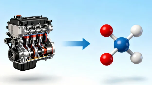
Unexpected spikes in diesel generator fuel consumption indicate more than just inflated operational overhead—they are critical indicators of underlying mechanical or thermal inefficiency. When a genset burns extra fuel to sustain its electrical output, it usually points to poor air-fuel ratios, component wear, or systemic mismatching. This guide diagnoses five high-frequency mechanical faults that drive up fuel overhead, providing field-tested parameters, troubleshooting steps, and actionable cost-control strategies to recover up to 30% in wasted fuel expenses.

1. Air Intake Restriction: The Silent Air-Fuel Imbalance

In dusty operating environments like mines or construction sites, air filters rapidly load with particulate matter. This restriction suffocates the combustion chamber, shifting the air-fuel ratio toward a “rich” mixture. The resulting incomplete combustion manifests as heavy black smoke and delayed transient load response.

For instance, a standard 1000kW prime-rated diesel generator running with a severely restricted air filter will increase its hourly fuel burn by 8 to 10 liters just to compensate for the lost thermal efficiency. Engineers should not wait for a complete failure; intake negative pressure must be verified using a restriction gauge. If the intake vacuum exceeds 25 kPa, filter element saturation has occurred.

Field Remedy: Replace loaded elements with high-efficiency, pleated media (such as Donaldson heavy-duty variants). Under standard operating conditions, service intervals should be set at 500 hours, dropping to 200 hours in severe, high-dust environments to maintain baseline fuel metrics.

2. Fuel Injection Inefficiency: Nozzle Coking and Pump Wear

The injection system is the heart of diesel thermal efficiency. Nozzle coking—where carbon deposits build up around the injector spray holes—distorts the targeted atomization pattern. Instead of a fine, uniform mist, fuel enters the cylinder in large droplets, leading to irregular combustion, cylinder washing, and a 20% to 30% surge in raw fuel consumption. At the same time, internal wear within the high-pressure fuel pump’s plunger pairs drops operating pressures below peak performance levels.

Consider a real-world example from a standby data center generator: a single-cylinder injector failure caused by carbon buildup altered the unit’s fuel efficiency profile, driving up fuel consumption from a standard 198 g/kW·h to over 245 g/kW·h under identical loads. Diagnostic verification requires extracting the fuel injectors using specialized pulling wrenches to measure the nozzle orfices (typically ranging between 0.3mm and 0.5mm) and running a pressure test on the pump train. If the pump rail pressure drops below 20 MPa (against a standard baseline of 25-30 MPa), the plunger assembly requires rebuilding.

Field Remedy: Rather than opting for immediate, costly component replacement, place the fouled injectors into an ultrasonic cleaning bath. Re-calibrating the cleaned injectors on a specialized pump test stand can restore original spray profiles, saving up to 70% in hardware replacement costs while normalizing fuel consumption.

3. Sensor Degradation: Electronic Misjudgment by the ECU

Modern diesel engines rely heavily on electronic control units (ECUs) to adjust fuel rail pressures and injection timing based on sensory feedback. When critical sensors—such as the magnetic speed pickup or the fuel temperature sensor—drift out of calibration, they feed skewed data to the control loop. The engine might be handling a steady, moderate load, but a degraded sensor forces the ECU to miscalculate the load profile, falsely inflating the injection pulse width.

On high-horsepower platforms like the Cummins QSK60 engine, a malfunctioning speed sensor can cause the ECU to perceive false load fluctuations, automatically over-indexing the throttle mechanism and inflating fuel tracking metrics by 15% to 25%. Technicians can diagnose this by checking the sensor’s internal resistance with a digital multimeter; standard values should measure between 500 and 800 ohms. Any readings showing open circuits or dead shorts require immediate replacement.

Field Remedy: Connect a dedicated diagnostic terminal (such as the Cummins INSITE interface) to cross-reference real-time sensor telemetry against physical flow meters. Always source OEM-spec replacement sensors. Low-grade aftermarket components often exhibit tolerance variances up to 12%, which perpetuates fuel tracking errors.

4. Load Profile Mismatch: The Core Cost of Low-Load Operation

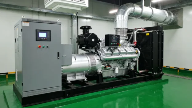
Running a heavy industrial diesel generator under significantly low loads—often referred to as “using a big horse to pull a small cart”—is one of the most widespread causes of fuel waste. Operating a 300kW generator to handle a continuous 50kW demand drops the engine far below its optimal thermal efficiency curve, increasing specific fuel consumption per kilowatt by more than 40% compared to rated conditions.

Field data from a construction site illustrates this clearly: a 100kW prime unit was deployed to run a minor 20kW electrical lighting load, burning approximately 28 liters per hour. When the load profile was re-engineered to sit within the optimal 60% to 80% capacity window, the specific fuel consumption dropped sharply to just 18 liters per hour for an equivalent power metric. Low-load operation also causes “wet stacking,” where unburnt fuel and carbon accumulate in the exhaust elbow, threatening long-term engine health.

Field Remedy: Install automatic paralleling switchgear to dynamically distribute site loads across a multi-genset configuration, ensuring every running engine operates within its most efficient window. For isolated loads under 100kW, replace oversized assets with dedicated compact power units (such as the Perkins 1104D series) to boost net fuel efficiency by up to 35%.

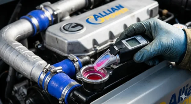
5. Thermal and Mechanical Neglect: Scaling and Carbon Accumulation

Internal engine maintenance directly dictates how effectively chemical fuel energy converts into mechanical rotation. If the cooling jacket accumulates just 1mm of calcium scale or mineral crust, internal heat rejection drops significantly. This raises localized cylinder head temperatures by roughly 15°C, causing oil thinning and accelerated piston ring friction. Furthermore, heavy carbon scaling on the valve seats compromises compression ratios, dropping net thermal efficiency by over 10%.

Field Remedy: Implement a rigorous deep-clean cycle every 2000 operating hours. Flush the cooling passages with a specialized 8% citric acid solution for 4 to 6 hours to clear scale, which typically drops operating temperatures by 8°C to 10°C. For the combustion top-end, perform media blasting (such as walnut shell blasting) across the cylinder heads to remove stubborn carbon crusts and restore compression pressure back above 90% of original factory specifications.

Industrial Fuel Efficiency Optimization Matrix

Diagnostic Focus Essential Field Tools OEM Specification Target Expected Fuel Recovery
Air Intake Tract Vacuum Manometer, Restriction Gauge Intake Vacuum Pressure < 25 kPa Recovers 15% – 20% waste
Fuel Injectors Nozzle Tester, Ultrasonic Cleaning Bath Rail Injection Pressure: 25 – 30 MPa Reduces fuel burn by 20% – 30%
ECU Sensor Loop Digital Multimeter, Diagnostic Scanner Pick-up Internal Resistance: 500 – 800 ohms Eliminates 15% – 25% false scaling
Load Management Power Quality Analyzer, Sync Switchgear Targeted Operating Load: 60% – 80% Saves 25% – 40% in fuel costs
Thermal Core Chemical Flush Kit, Walnut Blaster Coolant Temperature Range: < 85°C Improves thermal efficiency by 8% – 12%

Operational Framework: Implementing the “Three Checks & Three Changes” Rule

To institutionalize these fuel savings, fleet operators should establish a standardized preventative maintenance workflow:

  • The Daily Three-Check Routine: Inspect filter differential pressure indicators prior to startup, monitor real-time sensor warning logs during active operation, and audit exhaust stack clear-color profiles upon system shutdown.
  • The Scheduled Three-Change Protocol: Mandate air filter element replacements at 500 hours, swap primary fuel and water-separator elements at 2000 hours, and renew lubricating oil filtration elements at 4000 hours.
  • Digital Fuel Telemetry: Integrate digital fuel monitoring systems (such as the Schneider Easergy series) into the genset control panel to map consumption curves in real time, configuring telemetry alerts to flag any sudden 10% efficiency drops.

Structured maintenance schedules do more than just cut fuel burn by 30%—they extend the operational life of your industrial generator by 20% to 30%. For a targeted fuel optimization plan tailored to specific engine families (such as Cummins, Caterpillar, or Weichai platforms), contact our engineering desk with your specific model number for a customized technical brief.