作者归档:奥联发电机

4 Wheels Mobile Diesel Generator Set | Field Construction Genset

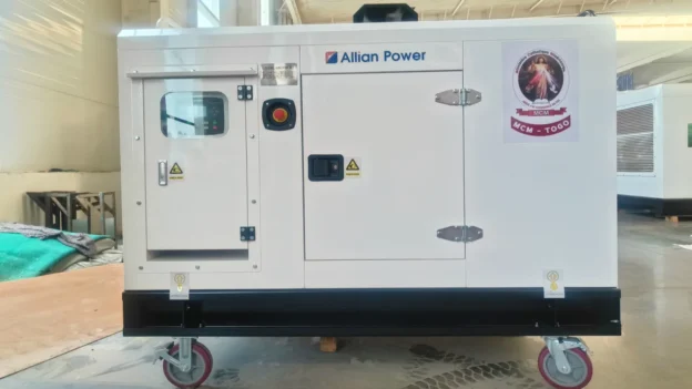
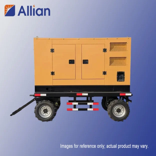
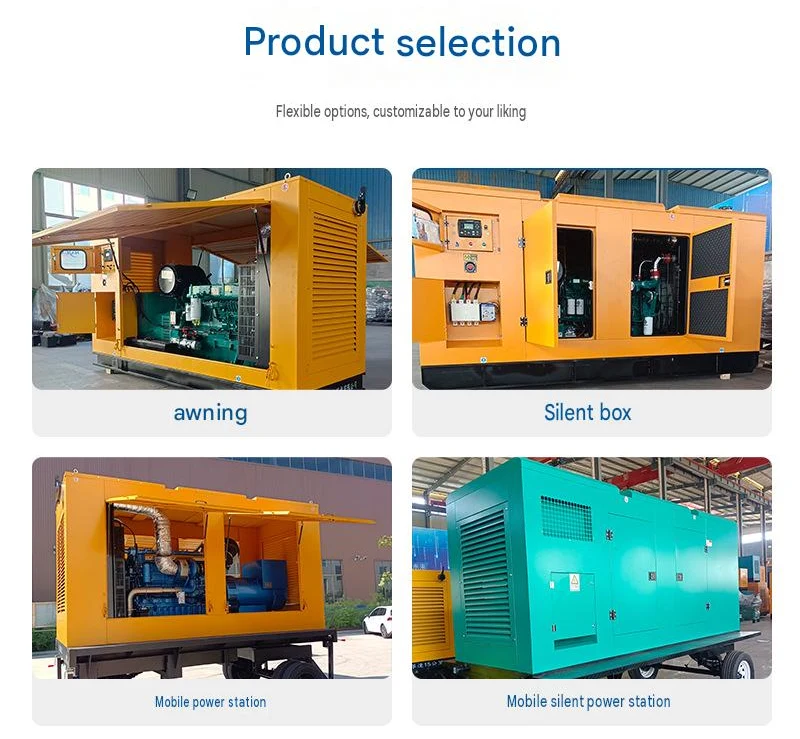
The 4-wheel mobile diesel generator set is a heavy-duty mobile power solution specially designed for harsh field engineering conditions. Adopting a four-wheel load-bearing structure and integrated channel steel frame chassis, it features low center of gravity, strong bearing capacity and excellent all-terrain trafficability, suitable for long-distance towing and complex road transportation.

Matched with famous brand diesel engines including Cummins, Perkins, Volvo, Weichai and Yuchai, the unit delivers stable power output and reliable performance. It is equipped with a professional pneumatic/hydraulic braking system and 180° flexible steering turntable, which can synchronously brake with the towing vehicle to ensure driving safety. The high-strength galvanized steel shell is anti-corrosion, rainproof and dustproof, adapting to long-term outdoor construction operations.

The unit is equipped with hydraulic support doors, real-time operation observation windows, emergency stop devices and on-board lighting systems. Four-corner mechanical support legs ensure stable operation without displacement. With a power range covering medium and high power sections, it is the preferred mobile power equipment for municipal engineering, road construction, mining operations and large-scale field projects.

Product Features

  • Heavy-duty 4-wheel structure, strong load-bearing and stable driving
  • Low center of gravity design, anti-tilt and high safety
  • Flexible 180° steering, suitable for complex road conditions
  • Complete braking and stabilizing system
  • Durable galvanized shell for long-term outdoor use
Product Name 4 Wheels Mobile Diesel Generator Set
Wheel Structure 4 Heavy-duty Load-bearing Wheels
Steering Mode 180° Flexible Turntable Steering
Braking System Pneumatic / Hydraulic Synchronous Braking
Applicable Power Range 50kW ~ 800kW
Core Advantage Stable Transportation, Strong Terrain Adaptability
Main Applications Road Construction, Mining, Municipal Engineering, Large Field Projects

A Complete Buying Guide for Diesel Generator Sets | Selection & Configuration Tips

Selecting a diesel generator set is a systematic project. It is not advisable to make decisions merely based on price and nominal power. Wrong selection may lead to sharply increased operating costs, frequent equipment failures, or even power failure at critical moments. The design and installation of generator sets must be completed by professional engineers, including exhaust backpressure calculation, ventilation calculation, paralleling system commissioning, etc. This article summarizes core selection criteria of diesel generator sets, divided into five main sections and multiple key evaluation dimensions, to help customers build a clear and complete decision-making framework.

1. Clarify Your Core Requirements

1.1 Confirm the Main Application

(1) Prime Power: Used as the main continuous power source for long-time operation, widely applied in remote mining sites and areas with insufficient grid power. You need to select models rated at prime power with sufficient load margin.

(2) Standby Power: Only activated when grid power fails, with limited annual operating hours. Typical scenarios include buildings, hospitals and data centers. Standby power models are adopted, and standby power rating is normally around 10% higher than prime power.

Important Note: Never use a standby-rated generator set for continuous prime power service. It will drastically shorten engine service life.

1.2 Calculate Total Power Capacity

(1) List all loads: Record all powered equipment and their rated power (kW) or rated current (A).

(2) Distinguish load starting characteristics:

  • Resistive loads (lights, electric heaters, etc.): Starting current is almost equal to running current.
  • Inductive loads (motors, compressors, etc.): Inrush starting current can reach 5–7 times running current, which is the most easily overlooked point in selection.

(3) Total power calculation:

  • Steady-state power: Sum of power consumption when all devices run simultaneously.
  • Inrush starting power: Calculated by adding the starting inrush current of the largest motor to running current of other equipment.
  • Safety margin: Reserve 10%–25% power margin on the calculated maximum total load. Avoid long-term full-load operation and reserve space for future capacity expansion.

1.3 Confirm Site Working Conditions

(1) Ambient temperature: Generator sets need derating under high-temperature environment.

(2) Altitude: The higher the altitude, the thinner the air, and the more severe engine power derating. Normally, power drops by about 3% per 300m rise in altitude. Power correction must be carried out according to altitude.

(3) Installation space: It determines unit dimension, heat dissipation solution and layout, and judges whether a soundproof canopy or mobile trailer is required.

2. Evaluate Technical Specifications & Performance

2.1 Engine

(1) Brand & reputation: Prioritize globally well-known brands (Cummins, Perkins, Volvo, MTU, Deutz, etc.) or their licensed products for stable quality, performance and after-sales support.

(2) Technical types:

  • Mechanical pump engine: Mature technology and lower procurement cost, but sensitive to fuel quality with lower emission level.
  • Electronic governor engine: Higher governing accuracy and stable output frequency, suitable for loads with strict frequency requirements.
  • Electronic fuel injection engine: Precise fuel control, fast response, low emission and energy saving, which is the mainstream solution on the market.

2.2 Alternator

(1) Brand & type: Prefer famous brands including Stamford, Leroy-Somer, Marathon.

(2) Insulation class: Minimum Class H to guarantee stable operation under high temperature.

(3) Protection class: Basic requirement IP23 to resist water droplets and solid foreign objects. Outdoor units are recommended to upgrade to IP54.

2.3 Control System

(1) Basic control: Manual start and basic fault protection.

(2) Automatic control (AMF): Recommended as standard. It can detect grid failure automatically, start the unit and close switch for power supply. When mains power recovers, it switches back to grid and controls unit cool-down shutdown.

(3) Cloud intelligent monitoring: Remotely check unit status, operating parameters and receive fault alarms via 4G/5G/Ethernet, realizing unattended operation and maintenance.
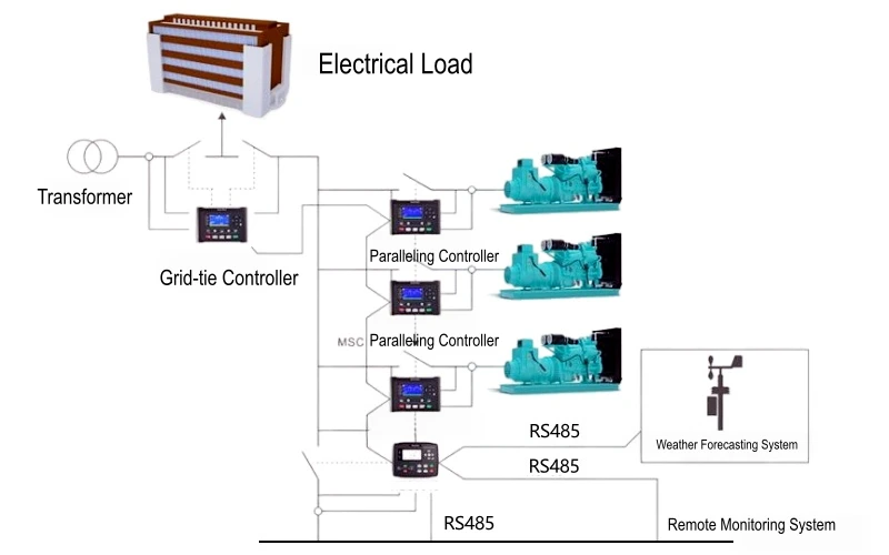
Working Principle of Parallel Power Supply for Diesel Generator Sets

3. Configuration of Each Subsystem

Auxiliary systems of diesel generator sets are the core guarantee for long-term, efficient and stable operation. Poor auxiliary configuration will lead to frequent failures even if the main engine is of good quality. The following introduces configuration points of each auxiliary system in detail.

3.1 Fuel System

Function: Store, deliver and filter fuel to ensure clean and sufficient fuel supply to the engine.

(1) Fuel storage devices:

  • Base-mounted fuel tank: Integrated under the unit with limited capacity, generally supporting 4–8h continuous power supply, easy installation. Large projects or long running time require an external fuel tank.
  • Large external fuel tank: Customizable volume according to target running duration (24h /48h); equipped with fuel transfer pump to deliver fuel to daily service tank.
  • Oil storage tank: Above-ground or underground tank farm for ultra-long continuous operation or strategic fuel reserve.

(2) Fuel delivery & filtration:

  • Fuel transfer pump: Mandatory if the tank is installed lower than engine to maintain fuel supply pressure.
  • Water-oil separator: Critical component! Separates moisture from fuel and prevents corrosion and damage of fuel injection parts.
  • Dual-stage fuel filter: Install extra primary or fine filter before original engine fine filter for double protection and longer filter service life.
  • Piping: Use standard seamless copper tube or galvanized steel pipe. Non-metallic pipes are forbidden due to aging and flammability risks.

3.2 Air Intake System

Function: Supply sufficient, clean and cool air for engine combustion.

(1) Air filter:

  • Dry-type air filter: Widely used, cartridge needs regular replacement.
  • Oil bath air filter: Suitable for heavy dust mining sites with different maintenance routine.
  • Filtration efficiency: Choose high-efficiency filter to better protect engine.

(2) Intake pipe: Draw fresh outdoor air. Keep pipeline as short and straight as possible with fewer elbows to reduce airflow resistance.

(3) Intake silencer: Optional for projects with strict noise control in generator room.

Key Point: Air inlet must be placed outside the generator room with good ventilation and low temperature. Do not draw hot air inside the room, otherwise power derating will occur.

3.3 Exhaust System

Function: Efficiently discharge high-temperature exhaust gas and greatly reduce exhaust noise.

(1) Flexible bellows: Mandatory part. Installed after engine exhaust outlet to absorb unit vibration, avoid vibration transmission to flue pipe and prevent weld cracking or equipment damage.

(2) Silencer, classified by noise reduction requirement:

  • Industrial silencer: 15–20 dBA noise reduction
  • Residential silencer: 20–30 dBA noise reduction
  • Super silencer: ≥30–40 dBA noise reduction, for ultra-quiet scenarios

(3) Exhaust pipe:

  • Material: High-temperature resistant seamless carbon steel pipe. Ordinary water pipe and galvanized pipe are strictly prohibited (zinc coating releases toxic flue gas under high temperature).
  • Slope: Pipe slopes towards engine to avoid condensate water backflow into engine.
  • Backpressure: Total backpressure of the whole system (silencer + pipe + elbows) cannot exceed engine manufacturer’s maximum allowable value (usually <5kPa). Increase pipe diameter for long pipelines and many elbows.
  • Rain cap: Install rain cap at pipe end to block rainwater and debris.

3.4 Cooling System

Function: Remove heat generated by engine timely and maintain optimal operating temperature range.

(1) Radiator & fan:

  • Integrated radiator with fan: Standard configuration for most units. Fan blows backward for heat dissipation. The generator room must have sufficient air inlet and outlet to exhaust hot air.
  • Remote radiator: Adopted when unit is installed in closed room and hot air cannot be discharged directly. Radiator is placed outdoors and connected to engine via water pipes.
  • Cooling tower: Solution for large units with closed circulating water cooling and better heat dissipation effect.

(2) Coolant: Use qualified antifreeze coolant. Tap water is not allowed to avoid scaling, corrosion and cracking in winter.

3.5 Control System & Electrical Interface

Function: Realize automatic control, condition monitoring, fault protection and safe load connection.

(1) Automatic Transfer Switch (ATS): Core part of standby power system. Continuously monitor grid quality; send start signal to generator set when mains fails, switch load to generator after power quality stabilizes; switch back to grid automatically after mains recovery and control unit cool-down shutdown.

(2) Battery: High-quality starting battery with acid-proof, explosion-proof battery cabinet.

(3) Intelligent charger: Keep battery fully charged to guarantee reliable startup. Charger is powered by mains, and charged by generator when power fails.

(4) Paralleling system: For large projects and N+1 redundant power supply scenarios, paralleling cabinet and synchronous controller are equipped to realize parallel operation of multiple units and unified load distribution.

Overview of Auxiliary System Configuration for Diesel Generator Sets
Auxiliary System Core Components Configuration Points & Purposes
Fuel System Daily fuel tank, fuel transfer pump, oil pipe, filter Ensure continuous, clean and sufficient fuel supply to extend engine service life.
Air Intake System Air filter, silencer, pipeline Supply sufficient air, reduce intake noise and guarantee combustion efficiency.
Exhaust System Flexible elbow, silencer, exhaust pipe, rain cap Discharge exhaust gas efficiently, reduce back pressure and noise, prevent rainwater intrusion.
Cooling System Radiator, fan, thermostat, water pump Maintain engine at optimal operating temperature to avoid overheating shutdown and wear.
Exhaust System Flexible elbow, silencer, exhaust pipe, rain cap Discharge exhaust gas efficiently, reduce back pressure and noise, prevent rainwater intrusion.
Control System Control panel, battery, charger, ATS Realize automatic control, monitoring, protection and automatic switching with mains power.
Starting System Battery, battery cabinet, charger Provide reliable starting power to ensure successful startup at any time.
Paralleling System Paralleling cabinet, synchronous controller Enable parallel operation of multiple units to meet heavy load or redundancy requirements.

Conclusion

Do not treat a diesel generator as a single standalone machine, but regard it as a complete power system. Start from your actual site requirements and select suppliers with reliable technology and good after-sales service. Meanwhile, ensure installation, commissioning and later maintenance are implemented by professional teams. Only in this way can the generator set reliably carry loads and supply stable power at critical moments. In addition, auxiliary parameters such as tank capacity, exhaust pipe diameter and ATS current rating must perfectly match main engine power and site conditions. A well-configured auxiliary system can upgrade a diesel generator set from simple machinery into a reliable, intelligent and durable full power solution.
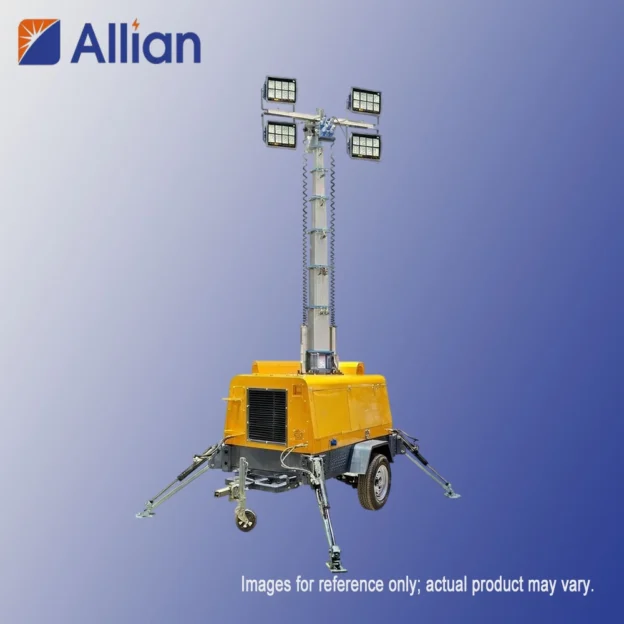
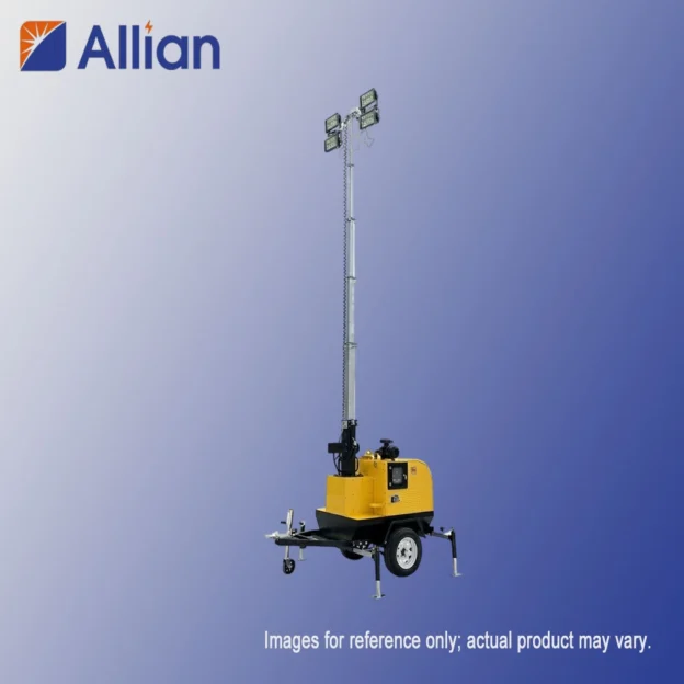
AL-4000D Diesel Light Tower (4x1000W Metal Halide, 9m Mast) | Allian Power

The AL-4000D is a heavy-duty diesel light tower for mining, construction and infrastructure projects that run through the night. A 110 L fuel tank delivers up to 65 hours of continuous light – nearly a week of night shifts on a single fill.

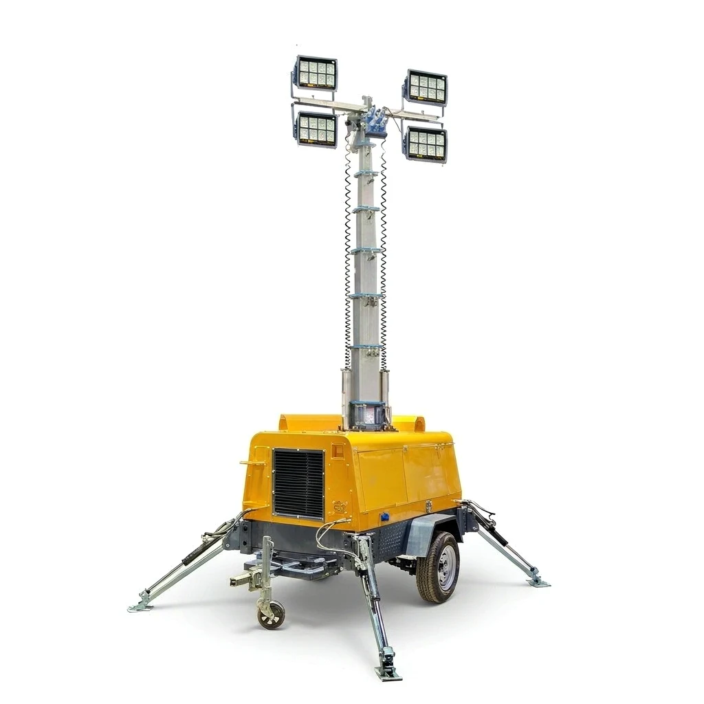
AL-4000D diesel mobile light tower full unit overview
AL-4000D Full Unit Overview
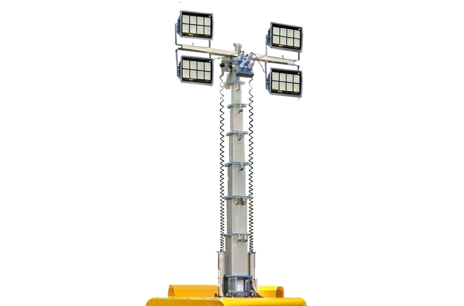
AL-4000D metal halide lamp head and three-section telescopic mast close-up
Lamp Head & Mast
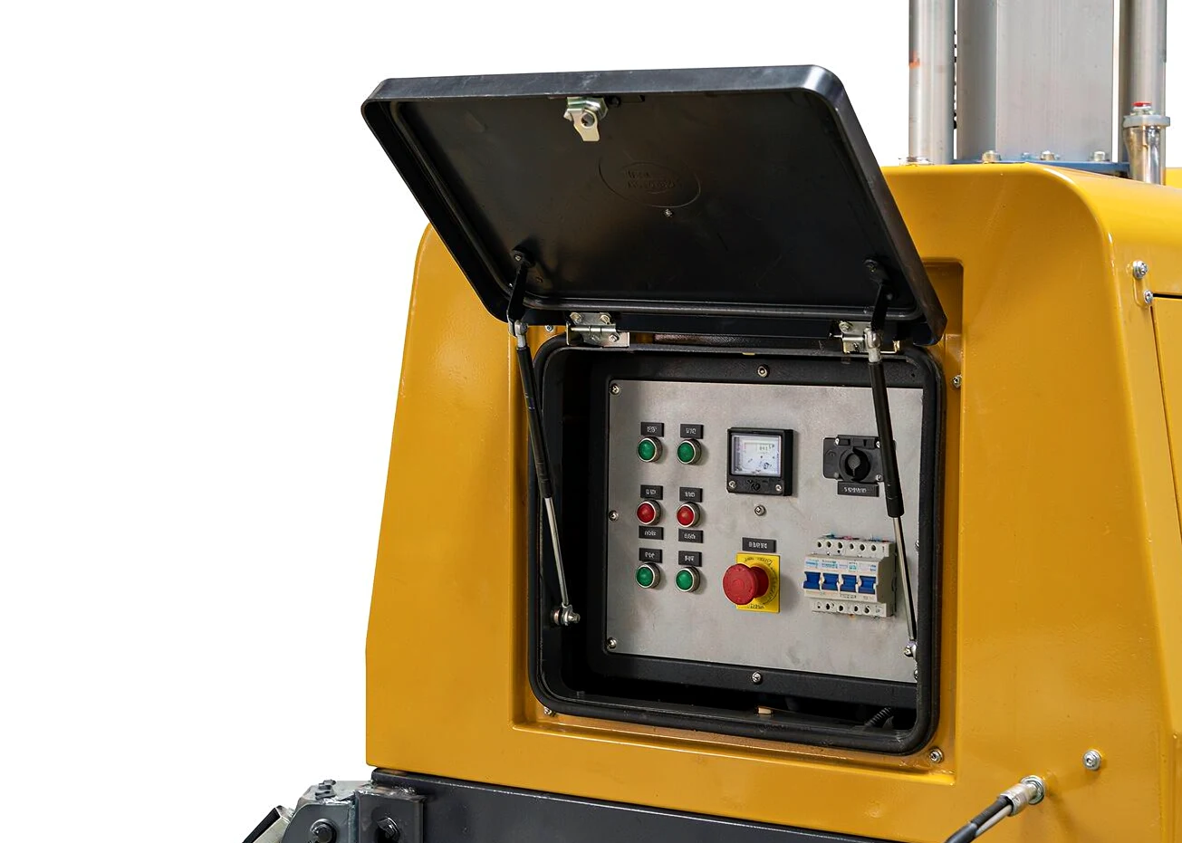
AL-4000D integrated control panel with rain cover close-up
Integrated Control Panel
KEY FEATURES

Multi-Cylinder Diesel Power

Yanmar, Kubota, Changchai or FAW Xichai engines from 11.1 to 20 kW – water-cooled and built for round-the-clock duty.

440,000 lm of Metal Halide Light

Large-flux, long-life illumination from 4×1000 W floodlights.

9 m Three-Section Mast

Galvanized, anti-drop and corrosion-resistant, with a long irradiation throw.

Self-Braking Winch

Hand-crank lifting with an adjustable irradiation angle.

Five Windproof Support Legs

A rock-solid stance up to 20 m/s wind.

Rain-Covered Control Panel

Integrated operation panel protected from the weather.

65 Hours Per Fill

The 110 L tank covers a full week of night shifts without refueling.

LIGHT SOURCE
Lamp Configuration 4 x 1000 W metal halide floodlight
Luminous Flux 440,000 lm
DIESEL ENGINE OPTIONS
Engine Brand Engine Model Cylinders Power
FAW Xichai 4DW81-23D / 4DW81-28D 4 17 / 20 kW
Yanmar 3TNV76-GGE 3 11.1 kW
Changchai 380 / 3M78 3 14.3 / 11.5 kW
Kubota D1105 / EPAD1105 3 12.6 kW
GENERATOR & ELECTRICAL
Frequency 50/60 Hz
Rotate Speed 1500/1800 rpm
Combustion / Intake E-TVV, natural aspiration
Alternator Brushless, Class H insulation
Rated Voltage 230/240-120 V
Insulation Class Class H
Protection Rating IP23
Start-up Method Key start
MAST & LIFTING SYSTEM
Mast Sections 3-section
Lifting Mode Hand crank (self-braking)
Max Lifting Height 9 m
Wind Resistance 20 m/s
Noise Level 72 dB(A) at 7 m
TRAILER & DIMENSIONS
Suspension & Brakes Leaf spring suspension & single axle without brakes
Towbar With retractable guide wheel adjustment lever
Overall Length 3,650 mm
Overall Width 1,700 mm
Overall Height (Folded) 1,700 mm
Tire & Rim Size 14 inch
Fuel Tank Volume 110 L
Continuous Working 65 hours
TYPICAL APPLICATIONS
Where This Tower Works

Mining and quarrying, large-scale construction, rail and bridge projects, ports, oil & gas facilities, and disaster-relief operations that need days of autonomous lighting.


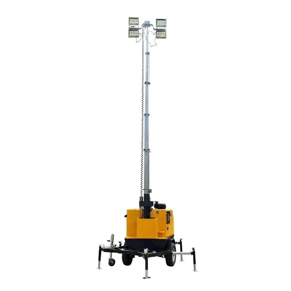
AL-1600E Electric-Lift Light Tower (4x400W LED, 9m, IP65) | Allian Power

The AL-1600E lifts its 6-section mast electrically and rotates 359° to place light exactly where the crew is working. An IP65 rating keeps the electrics alive in driving rain and dust.

AL-1600E Full Unit Overview
Lamp Head & Mast
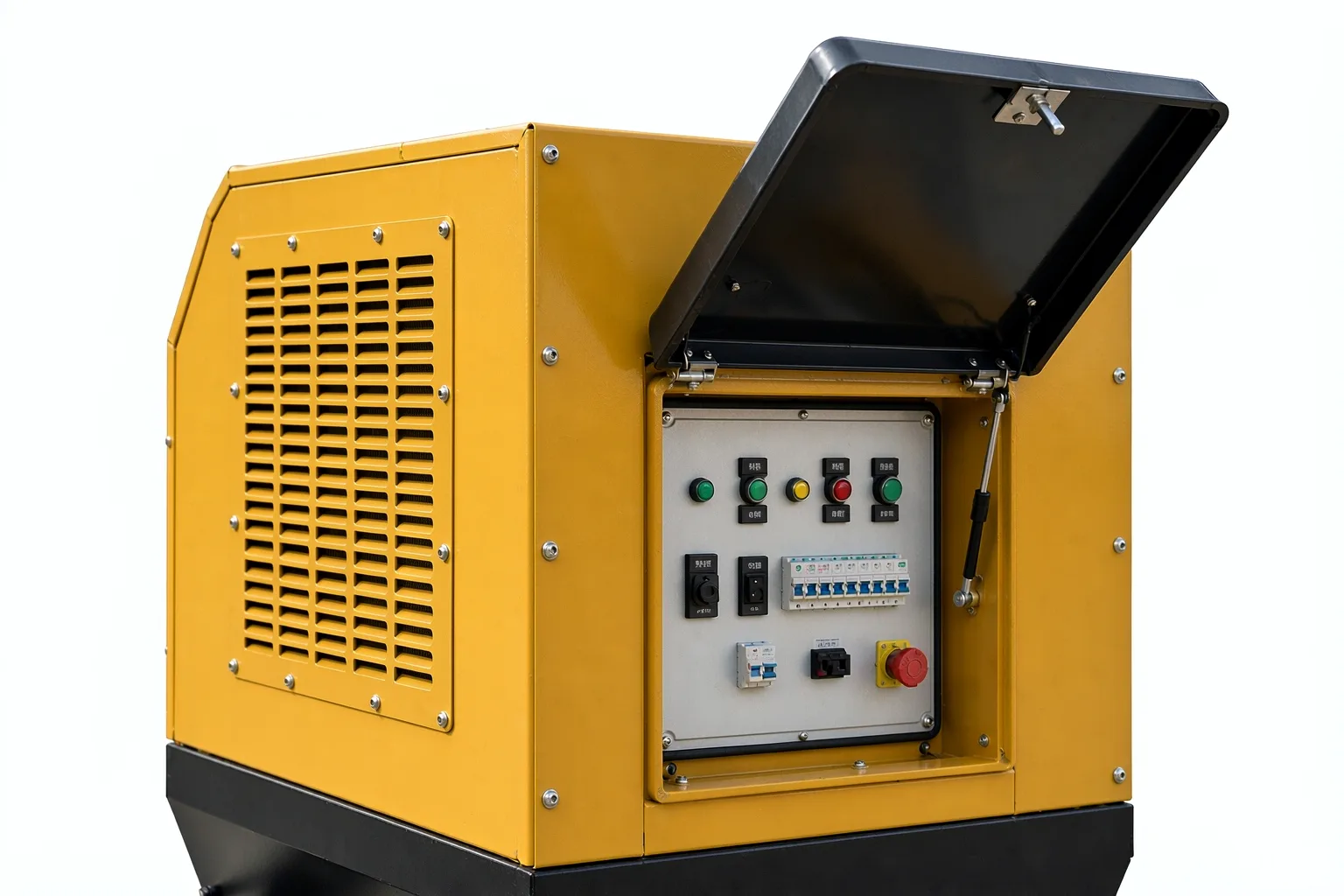
Control Panel
KEY FEATURES

Push-Button Mast

Electric lifting – no cranking, no hydraulics to service.

359° Self-Locking Rotation

Swing the light head to the work area and it stays put.

4×400 W LED Lighting

360,000 lm with long service life and low power draw.

Six-Section Galvanized Mast

Anti-drop, corrosion-resistant telescopic sections.

IP65 Protection

Sealed electrics keep working in driving rain and dust.

Five Windproof Support Legs

Rated for 20 m/s wind, fully deployed.

60 Hours Per Fill

The 100 L tank sees you through the longest night shifts.

LIGHT SOURCE
Lamp Configuration 4 x 400 W LED
Luminous Flux 360,000 lm
DIESEL ENGINE OPTIONS
Engine Brand Engine Model Cylinders Power
Kubota Z482 2 4.5 kW
Yanmar D1105 3 12.6 kW
Kohler 3TNV76 Water-cooled 4-stroke 11.1 kW
GENERATOR & ELECTRICAL
Frequency / Speed 1800 rpm
Rated Voltage 240 V
Alternator Brushless, standard fit
Insulation Class Class H
Protection Rating IP65
Continuous Working 60 hours
Fuel Tank Volume 100 L
Start-up Method Key start
MAST & LIFTING SYSTEM
Mast Sections 6-section
Lifting Mode Electric
Mast Rotation 359° max manual rotation, self-locking
Max Lifting Height 9 m
Wind Resistance 20 m/s
Noise Level 72 dB(A) at 7 m
TRAILER & DIMENSIONS
Suspension & Brakes Leaf spring suspension & single axle without brakes
Towbar With retractable guide wheel adjustment lever
Overall Length 2,450 mm
Overall Width 1,350 mm
Overall Height 2,650 mm
Tire & Rim Size 14 inch
TYPICAL APPLICATIONS
Where This Tower Works

Urban night construction, municipal maintenance, events and exhibitions, parking areas – sites where the tower is repositioned often and space is tight.

Complete Diesel Generator Operation & Maintenance Management Guide

The core philosophy of diesel generator operation management is anchored in four principles: prevention first, routine maintenance, standardized operation, and safety above all. Generator operation management is a systematic endeavor that spans the full equipment lifecycle—from installation and commissioning through to retirement.

Implementing rigid Standard Operating Procedures (SOPs) and comprehensive logging protocols directly extends equipment service life, mitigates unexpected power outages, and ensures generator sets start reliably, operate safely, and supply clean power when emergency standby or prime power is demanded.

1. Pre-Operational Inspection Protocols

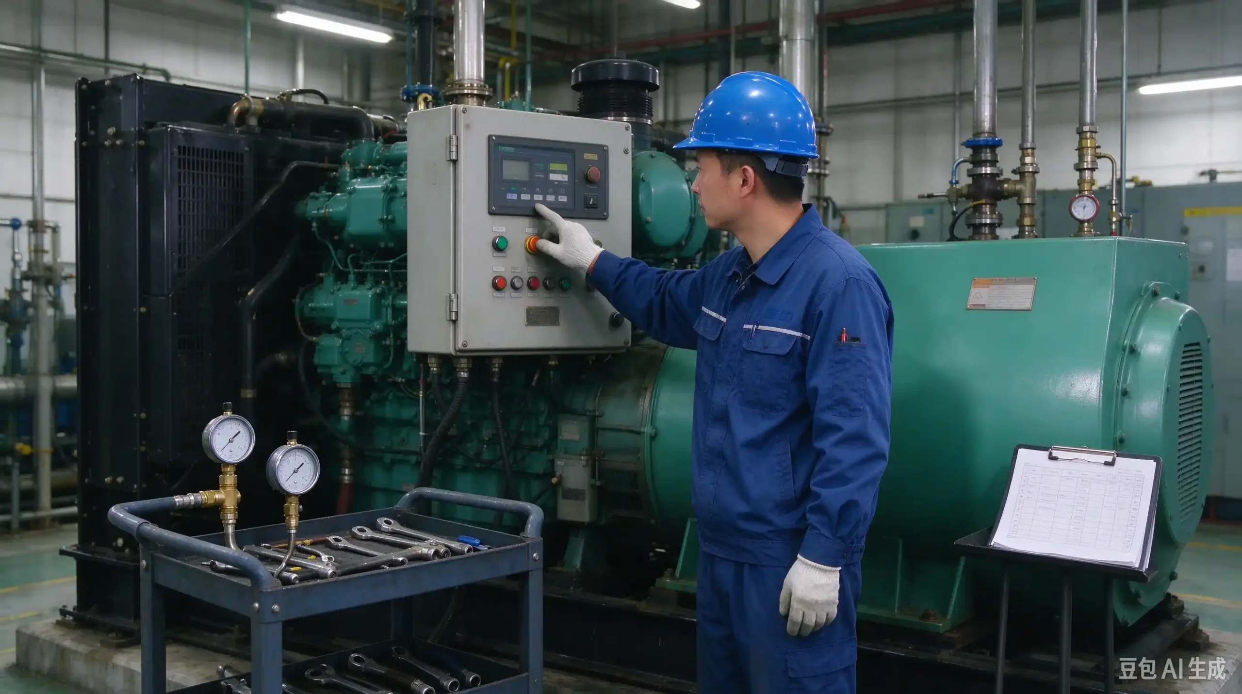
Before initiating any start cycle, operators must complete a rigorous multi-point visual and mechanical check to identify potential hazards and ensure operational readiness.

1.1 General and Environmental Inspection

  • Site Cleanliness: Ensure the generator enclosure and surrounding perimeter are free of debris, oil spills, rags, and combustible materials.
  • Structural Integrity: Inspect mounting baseplates, vibration isolators, pipe fittings, and electrical connections for loose hardware, damage, or active fluid leaks.
  • Ventilation Clearance: Verify that intake louvers and exhaust ducts are unobstructed to ensure unrestricted airflow for engine combustion and cooling.

1.2 Subsystem Inspections

  • Fuel System: Verify adequate diesel fuel levels in the day tank. Inspect fuel supply lines, lift pumps, and primary/secondary filters for leaks. Bleed trapped air from the fuel system if filters or fuel lines have been recently replaced.
  • Lubrication System: Check oil level via the engine dipstick; fluid must sit firmly between the MIN and MAX hash marks. Inspect oil color and viscosity; replace degraded oil immediately.
  • Cooling System: Inspect coolant level within the expansion tank or radiator header. Add recommended glycol coolant mixtures if low. Warning: Never open the pressure cap on a hot radiator. Check water pump seals and hose connections for leaks.
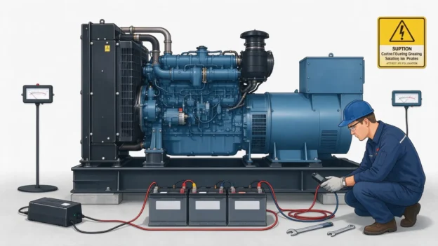
  • Starting Battery System: Measure battery terminal voltage using a multimeter—ensure a minimum reading of 12.6V for 12V systems or 25.2V for 24V systems. Confirm cable terminals are clean, tight, and greased to prevent corrosion.
  • Electrical Output & Load Interface: Ensure the main output circuit breaker is in the OFF (Open) position prior to starting under manual mode. Verify load cables are securely terminated and insulation remains intact.

2. Operational Procedures and System Management

2.1 Single-Unit Operating Sequence

  1. Pre-heating (If Equipped): In cold ambient environments, activate coolant or intake air preheaters via the control screen to warm up the cylinder block before cranking.
  2. System Power-Up: Turn the control panel key switch from OFF to ON. Verify display backlighting illuminates and digital controllers energize.
  3. Engine Startup:
    • If configured with idle/full-speed toggle options, start in idle mode. Limit idle warm-up runs to under 5 minutes to prevent carbon build-up.
    • Press the Start button. Crank the engine for a maximum of 5–10 seconds per attempt (do not exceed 30 seconds continuous cranking). If the engine fails to start, pause for at least 2 minutes before retrying to protect the starter motor and battery.
    • Note: Never attempt to hotwire or bypass the control panel to initiate a manual start.
  4. Loaded Running & Parameter Monitoring: Once the engine reaches rated speed and output voltage/frequency stabilizes, close the output circuit breaker to apply load. Regularly monitor control display parameters—including oil pressure, coolant temperature, AC voltage, current, and frequency—and log data into the operator logbook.
  5. Emergency Shutdown: Press the red Emergency Stop Button (E-Stop) ONLY during severe equipment malfunctions or electrical hazards. Avoid using E-stop for normal operational shutdowns.
  6. Normal Shutdown Procedure: Open the output circuit breaker to disconnect load. Allow the engine to run unloaded at rated speed for 3–5 minutes to cool down turbine housings and internal components. Press the Stop button on the panel to turn off the engine, then turn the key switch to OFF.

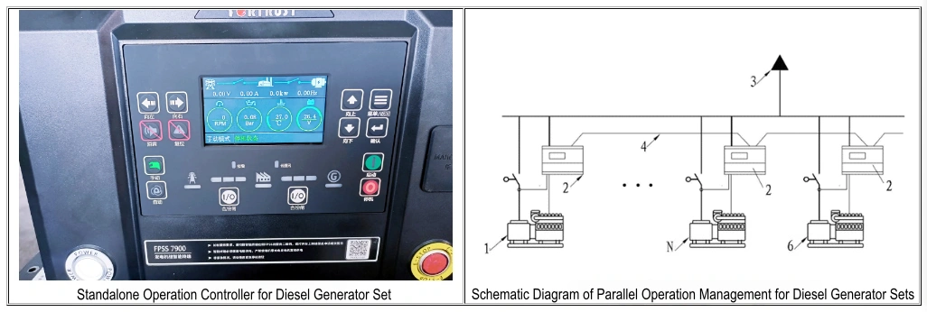
2.2 Multi-Unit Paralleling Management

For mission-critical applications like data centers or large industrial plants, multiple generator sets operate in parallel using a Master Controller and individual Generator Controllers linked via high-speed communication buses.

  • Automatic Demand-Based Power Management: Upon utility power failure, the master controller signals individual generator controllers to start a calculated number of units matching real-time load requirements, keeping an additional unit online in hot-standby (N+1 redundancy).
  • Synchronization Checks: Manual or automatic paralleling requires absolute matching across four conditions before closing tie breakers: equal voltage, identical frequency, correct phase sequence, and synchronized phase angle.

2.3 Operational Logging Standard

Accurate logging provides vital trend data for predictive diagnostics. Every run cycle should be recorded in a standardized log sheet.

Table 1 Diesel Generator Set Operation Record
Time Engine Parameters Generator Parameters Fault Record Operator Remarks
Start/Stop Time
Cumulative Operating Hrs
Oil Pressure Bar Water Temperature ℃ Voltage V Current A Frequency HZ Power KW

3. Post-Shutdown Protocols, Safety Rules & Maintenance

3.1 Post-Shutdown Checklist

  • Inspect engine bay for post-run oil, fuel, or coolant leaks (“Three Leaks”).
  • Close manual fuel supply valves if going offline for extended periods.
  • Verify generator main output circuit breaker is locked in the open position.
  • Reset auto-start standby units back to AUTO readiness mode for emergency deployment.
  • For long-term storage or major maintenance, disconnect battery negative terminals and drain fluids as required.

3.2 Comprehensive Safety Protocols

  • Personnel Safety: Only trained, certified personnel should operate or service generator sets. Wear PPE and avoid touching hot exhaust components (turbocharger, exhaust manifold). Disconnect battery cables before servicing electrical assemblies.
  • Environmental & Electrical Safety: Maintain proper room ventilation to prevent toxic Carbon Monoxide (CO) buildup. Collect waste oil and filters in compliant disposal containers. Always follow strict Lockout/Tagout (LOTO) procedures during electrical maintenance.

3.3 Preventative Maintenance Schedule (Hours-Based)

Maintenance Interval Required Maintenance Tasks
Daily / Weekly Execute full pre-start checklist; check battery voltage and fluid levels.
50 – 100 Hours Initial break-in maintenance: Replace engine oil and lube oil filter.
250 – 500 Hours Replace engine oil, lube oil filter, and fuel filters. Inspect/clean air filter element. Check belt tension and coolant protection levels.
1000 – 1500 Hours Replace all filters (oil, fuel, air). Flush cooling system and replace coolant. Inspect turbocharger, starter motor, and alternator bearings. Calibrate valve clearances and injectors.
Annual Maintenance Perform full load-bank testing (min. 4 hours at high load), recalibrate control sensors, and test safety protection trips regardless of run hours.
Extended Idle Rule Run idle standby generators under no-load for 30 minutes monthly; perform an annual load-bank test to burn off carbon deposits (wet stacking).

Conclusion

Effective management of diesel generator sets forms a closed-loop discipline: Standardized Operation → Active Monitoring → Detailed Logging → Preventive Maintenance → Continuous Improvement. By rigorously adhering to these operating and maintenance procedures, facility managers can ensure maximum equipment availability and reliable emergency power supply.

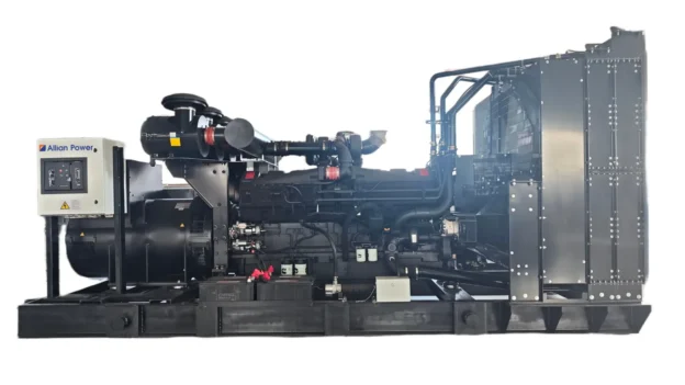
Cummins Diesel Generator Set: Core Components & Nameplate Guide

Cummins diesel generator sets are globally recognized for their exceptional stability, durability, and high performance. Serving as either primary or standby (emergency) power sources, they are extensively deployed across critical sectors, including telecommunications, healthcare, military operations, high-rise commercial buildings, rail transport, construction sites, mining, and oil exploration.These power systems can be customized into various operational configurations, such as open-frame units, soundproof enclosures, trailer-mounted mobile units, auto-start systems, intelligent remote-monitoring (“Three-Remote”) setups, and paralleling systems integrated with Automatic Transfer Switches (ATS). Mastering their primary components and correctly interpreting nameplate specifications is essential for efficient operation, preventive maintenance, and rapid troubleshooting.

1. Comprehensive Breakdown of Core Components

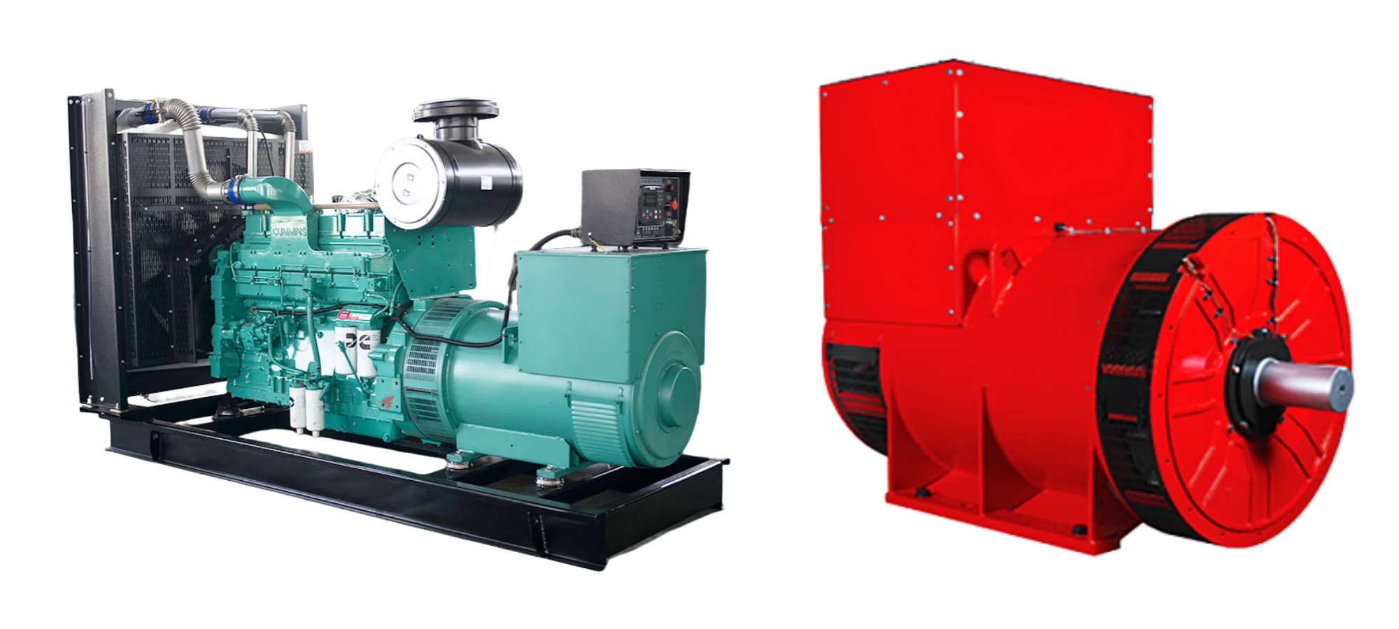
Achieving seamless, high-efficiency power generation relies on the synergy among three primary subsystems. Cummins generator sets combine industry-leading engine engineering with advanced emissions control, fuel efficiency, and noise-reduction technology.

Core Subsystem Primary Assemblies Core Functional Overview
Diesel Engine Cylinder block, crankshaft, pistons, fuel system (e.g., PT system), turbocharger, lubrication & cooling systems The primary power source; converts chemical energy in diesel fuel into mechanical energy. Its reliability directly dictates system output capacity.
Alternator Stator, rotor, excitation system (AVR / optional PMG) Converts mechanical energy into stable electrical energy, directly influencing voltage stability and current waveform quality.
Control System Control panel (Manual/Auto-Start/Remote), sensors, output circuit breaker Acts as the “brain” of the generator set, monitoring parameters, executing automatic control, providing fault protection, and enabling remote telemetry.

1.1 Diesel Engine: The Powerhouse

Serving as the engine heart, Cummins generator sets utilize trusted engine platforms manufactured by joint ventures and facilities such as Dongfeng Cummins (CCEC), Chongqing Cummins (DCEC), and Xi’an Cummins. Key design highlights include:

  • Proprietary Fuel Technology: Equipped with Cummins’ patented Pressure-Time (PT) fuel system, featuring low-pressure supply with high-pressure injection, exceptional reliability, and integrated overspeed protection. Most models incorporate Holset® turbochargers to optimize air intake and power density.
  • Heavy-Duty Architecture: Built with high-strength inline or V-configuration cylinder blocks, replaceable wet cylinder liners for easy overhaul, and 4-valve-per-cylinder designs for improved airflow and combustion efficiency.
  • Advanced Auxiliary Systems: Features variable-flow oil pumps that adjust lubrication dynamically to reduce parasitic power loss, along with forced liquid-cooling systems using gear-driven centrifugal pumps to maintain optimal thermal balance and reduce noise.

1.2 Alternator (Stamford Series)

Cummins power units typically integrate single-bearing, brushless, self-excited AC alternators from the STAMFORD® brand, engineered to IP23 protection standards and Class H insulation for harsh industrial environments.

  • 2/3 Pitch Winding Stator: Mitigates output voltage waveform distortion and minimizes winding heat accumulation.
  • Dynamically Balanced Rotor: Features robust damper windings to reduce voltage fluctuations under non-linear or shifting loads.
  • Automatic Voltage Regulation (AVR): Maintains steady-state voltage regulation within ±1% (or ±0.5% for precision applications). Optional Permanent Magnet Generator (PMG) excitation delivers superior motor-starting capabilities and immune performance against non-linear load interference (e.g., UPS, variable frequency drives).
  • Low EMI Output: Complies with Telephone Influence Factor (TIF < 50) and Telephone Harmonic Factor (THF < 2%), minimizing radio frequency interference.

1.3 Intelligent Control System

The control panel determines operational flexibility and system safety. Available in side-mount or top-mount configurations, controls range from standard manual startup modules to fully automated ATS interfaces and “Three-Remote” (telemetry, tele-signaling, tele-control) digital controllers.

  • Real-Time Diagnostics: Continuously monitors oil pressure, coolant temperature, engine RPM, running hours, output voltage, current, and frequency.
  • Automated Protection: Triggers immediate visual/audible alarms and emergency shutdowns upon detecting low oil pressure, engine overheating, or overspeed conditions.
  • Circuit Protection: Integrated molded-case circuit breakers (MCCB) protect the alternator from overcurrent surges and phase short-circuits.

1.4 Auxiliary Equipment

Standard complete packages include 40°C or 50°C heavy-duty ambient radiators, Fleetguard® air filtration systems, pulse dry exhaust manifolds with industrial silencers, starting batteries with rack assemblies, and anti-vibration rubber mounts.

2. Decoding the Equipment Nameplate

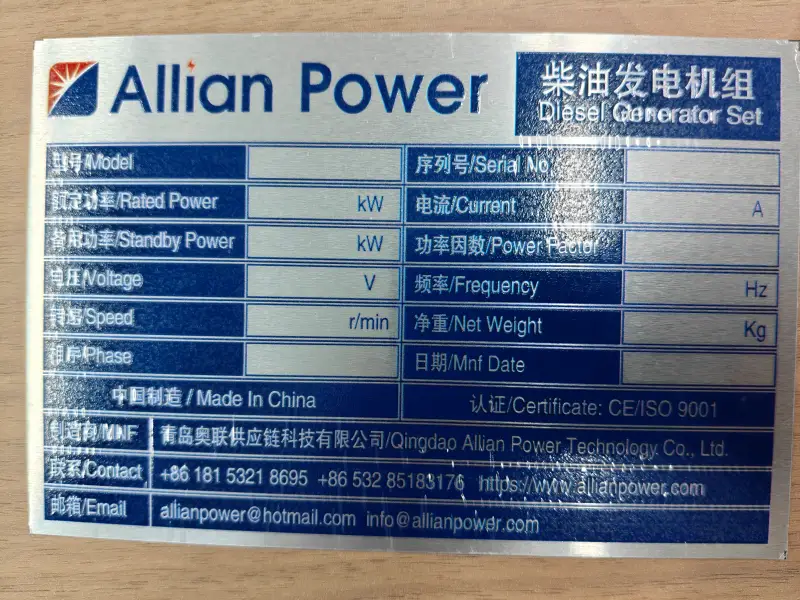
Every Cummins generator set carries a factory rating plate that serves as its unique official identifier. Accurate reference to the model number and serial number (S/N) is essential when ordering spare parts, requesting warranty service, or performing technical maintenance.

2.1 Key Information Recorded on the Nameplate

  • Generator Set Model: Expresses system capacity and engine series configuration (e.g., 6BTA5.9-G2).
  • Serial Number (S/N): A unique global identifier required to pull factory build sheets and warranty records.
  • Rated Power Output: Indicated in kW and kVA (typically calculated at a 0.8 lagging power factor). Distinguishes between Prime Power (PRP) and Standby Power (ESP).
  • Electrical Output Parameters: Rated voltage (e.g., 400V/230V), rated current (A), rated frequency (50Hz / 60Hz), and power factor.
  • Engine Speed: Standardized at 1500 RPM for 50Hz applications and 1800 RPM for 60Hz applications.
  • Manufacturing Details: Production date (month/year), IP enclosure rating (e.g., IP23), and factory origin (e.g., Chongqing Cummins Engine Co., Ltd.).

2.2 Engine Model Naming Convention (Example Breakdown)

Taking the Dongfeng Cummins 6BTA5.9-G2 engine as an example:

  • 6 — Number of cylinders (6 inline cylinders).
  • B — Cummins B-Series engine family.
  • T — Turbocharged.
  • A — Charge Air Cooled (Aftercooled / Intercooled).
  • 5.9 — Engine displacement in liters (5.9L).
  • G2 — Generator drive application code (version/iteration 2).

2.3 Best Practices for Managing Nameplate Data

  • Digital Archiving: Take a clear photo of the nameplate and record the serial number in the equipment service log immediately upon commissioning.
  • Derating Compliance: Always consult nameplate specs and factory derating charts when operating at high altitudes (above 1000m) or high ambient temperatures (above 40°C) to prevent overload thermal damage.
  • OEM Support: Always provide the full serial number when contacting authorized Cummins distributors for replacement parts or technical support to ensure 100% component compatibility.

Conclusion

Understanding the core mechanical and electrical subsystems of a Cummins diesel generator—alongside its nameplate ratings—enables operators to maximize operational uptime, streamline maintenance routines, and maintain site power security under all operating conditions.